In this blog post, we will be designing and programming an Arduino face recognition and face mask recognition project. The project would be able to recognize a user’s face with accuracy. It will also recognize a person when he/she is putting on a face mask. This is very important for organizations with personnel security and COVID-19 face mask policy. The project will be designed and programmed with Arduino pro-mini board and the System on Chip (SoC) Huskylenz module encased together with other peripheral modules. Ensure you read to the end to grasped the full details.
Arduino Face And Face Mask Recognition: The Components
| S/N | ITEMS | QUANTITY |
| 1 | 8×2 LCD MODULE | 1 |
| 2 | SWITCH (TOGGLE) TYPE | 1 |
| 3 | ARDUINO PROMINI BOARD | 1 |
| 4 | LiPo Charging Board | 1 |
| 9 | VERO BOARD | 1 |
| 10 | CONNECTING WIRES | 3 |
| 11 | PROGRAMMING AND LIBRARIES UPLOAD | 1 |
| 12 | GLUE GUM | 5 |
| 13 | GLUE GUN | 1 |
| 14 | SOLDERING IRON | 1 |
| 16 | 3.7V 4.8AH LiPo BATTERY | 8 |
| 17 | I2C LCD MODULE | 1 |
| 18 | HEADER PIN | 1 |
| 19 | HUSKYLENS AI MODULE | 1 |
| 20 | MISCELLENOUS |
Arduino Face And Face Mask Recognition: The Circuit Diagram
The Power Circuitry of The Project Design
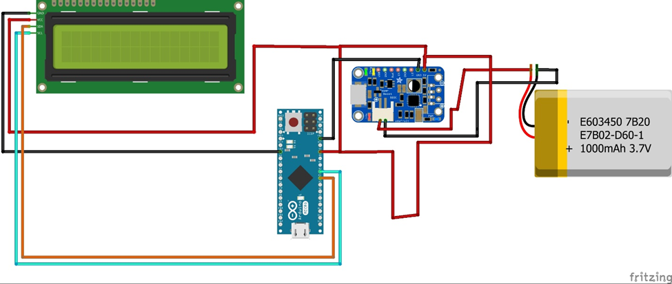
The design shows the connection of the Arduino pro mini to the LCD using an I2C module. The system uses the I2C pins of analogue pin 5 (A5) and analogue pin 4 (A4) to communicate with the liquid crystal display. the module is powered by 5V and 0V potential rails.
Since the system was mobile, it worked on using 3.7 V Li-Po battery. This was possible because the battery has a capacity of 4.8Ah in current rating. We used the charging module to charge the LiPo battery; since this module has an adjustable voltage output. We regulated the output using the onboard variable resistor of the LiPo charging module to give us 5V that will power the Arduino pro mini and Huskylenz AI module.
As shown above, the communication between these modules and the Arduino Pro-mini board is drawn. The source code would take care of the working of the modules provided these connections are kept this way.
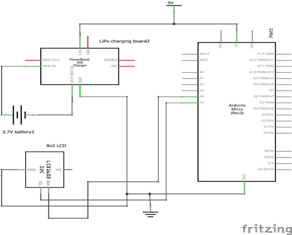
The Complete Schematic Diagram
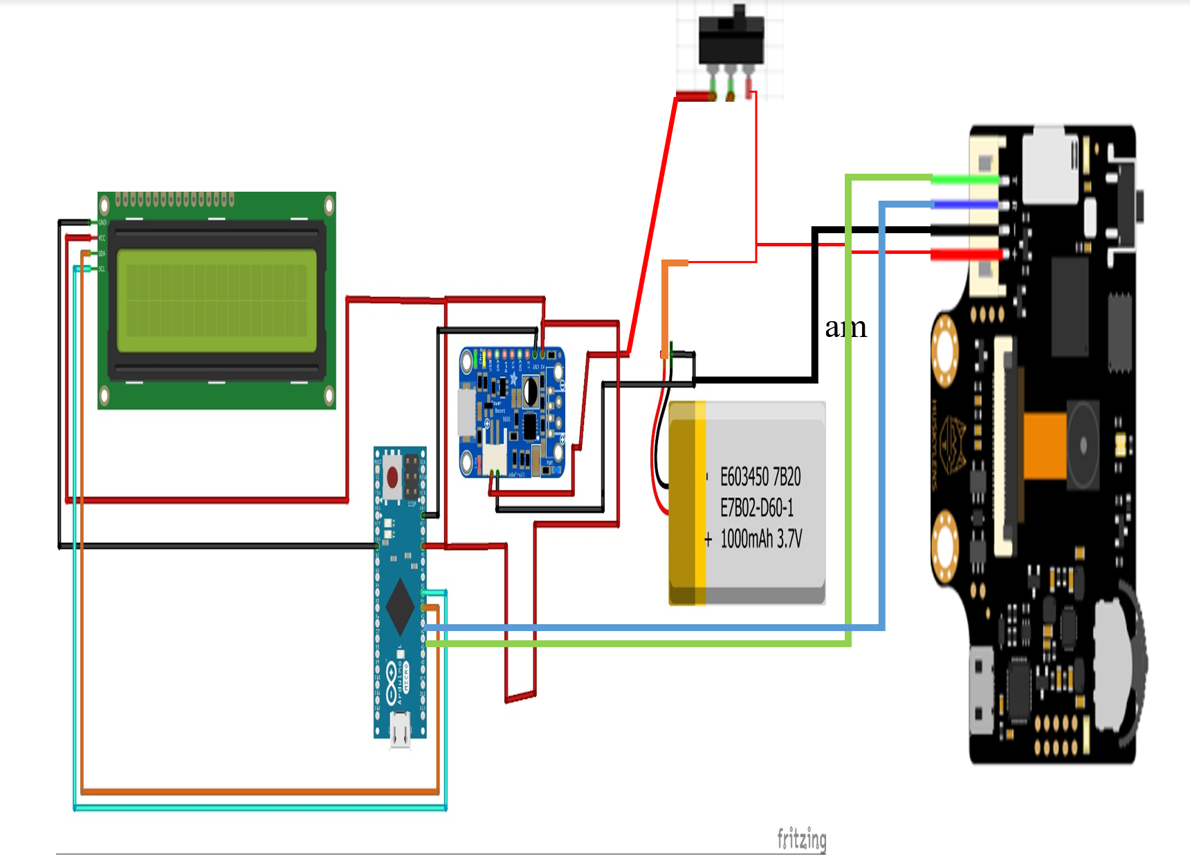
The schematic diagram shown above is the pictorial form. Here, the Huskylenz AI System on Chip (SoC) module has been connected. And also we have connected the power switch that would help us disconnect and connect power into the circuitry. The Huskylenz communicates with the Arduino via serial communication and hence two wires is connected to the Arduino digital pins for software serial protocol. The idea is to send serial prompts to the Arduino board when face recognitions of users are made. So that the Arduino can write to the LCD screen also relaying information to the user whose facials are being read.
All the power connections are connected as before. The Huskylenz module was however made to receive power as soon as the Arduino board was powered. The design was based off the DFrobots’ design on their wiki page. When powered, the Huskylenz would have to be manually operated to find the face recognition panel and initiate it. This means the design cannot run automatically but needs a human admin personnel to manage it effectively.
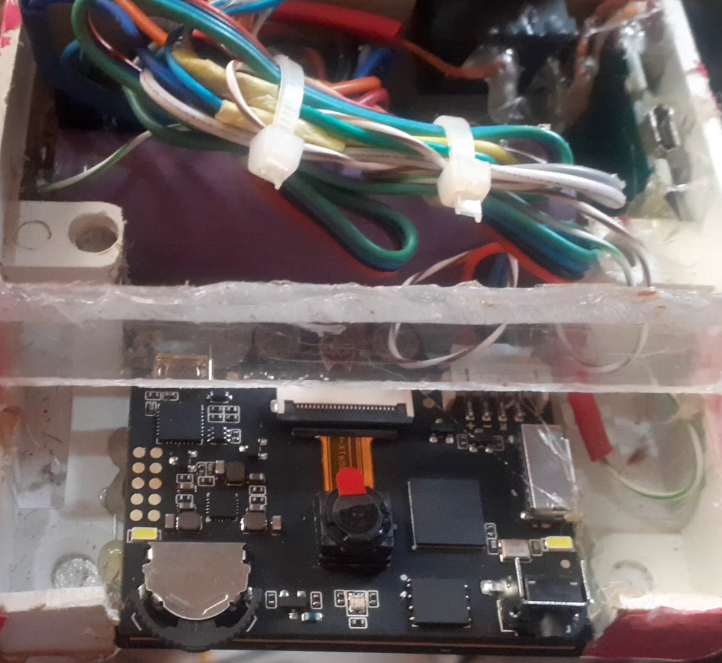
Encasing The Arduino Face And Face Mask Recognition Project
Now that we are done with the explanation of the schematic diagram, we can quickly solder this circuit and move to encasing and coupling the the components and module in a presentable and portable enclosure.
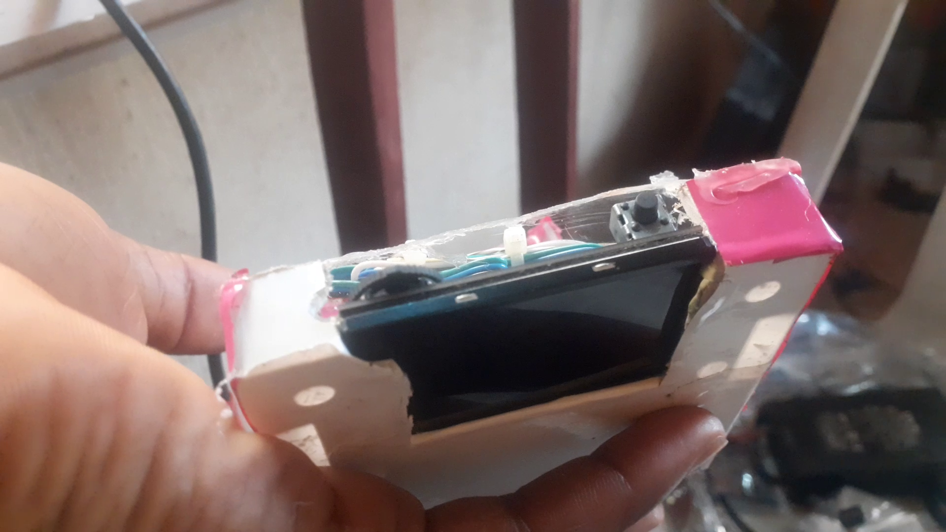
We used a small casing as this own shown here to construct the housing for the project design. The casing’s dimension is 3 by 3 inch in measurement. Some part of it was cut open and replaced with transparent glass so that the OV2 camera of the Huskylenz can see through and read the face of the users the design was presented to. The rest of the enclosure is basic fabrication and it is inexpensive to acquire.
Arduino Source code
// include the library code:
#include <LiquidCrystal.h>
#include "HUSKYLENS.h"
#include "SoftwareSerial.h"

HUSKYLENS huskylens;
SoftwareSerial mySerial(9, 8); // RX, TX
// initialize the library with the numbers of the interface pins
LiquidCrystal lcd(2, 3, 4, 5, 6, 7);

//HUSKYLENS green line >> Pin 10; blue line >> Pin 11
void printResult(HUSKYLENSResult result);

void setup() {
    Serial.begin(115200);
    mySerial.begin(9600);
    lcd.begin(8, 2);
       lcd.print("WELCOME");
       delay(3000);
       lcd.setCursor(0,0);
       lcd.print("FACE & ");
       lcd.setCursor(0,1);
       lcd.print("NOSEMASK");
       delay(2000);
       lcd.clear();
       lcd.setCursor(0,0);
       lcd.print(" RECOG-");
       lcd.setCursor(0,1);
       lcd.print(" NITION");
       delay(2000);
       lcd.clear();
       lcd.setCursor(0,1);
       lcd.print("PROJECT");
       delay(2000);
       lcd.setCursor(0,0);
       lcd.print("BLUE LED");
       lcd.setCursor(0,1);
       lcd.print("  ON ? ");
       //delay(2000);


    while (!huskylens.begin(mySerial))
    {
        Serial.println(F("Begin failed!"));
        Serial.println(F("1.Please recheck the \"Protocol Type\" in HUSKYLENS (General Settings>>Protocol Type>>Serial 9600)"));
        Serial.println(F("2.Please recheck the connection."));
        delay(100);
    }


     while (!huskylens.setCustomName("PRETTY", 0)) {
      Serial.println(F("ID1 customname failed!"));
      delay(100);
    }

   while (!huskylens.setCustomName("PRETTY", 1)) {
      Serial.println(F("ID1 customname failed!"));
      delay(100);
    }

    while (!huskylens.setCustomName("BEAUTY", 3)) {
      //Serial.println(F("ID1 customname failed!"));
      delay(100);
    }


while (!huskylens.setCustomName("BEAUTY", 4)) {
      Serial.println(F("ID1 customname failed!"));
      delay(100);
    }


    while (!huskylens.setCustomName("FINEST", 7)) {
      Serial.println(F("ID1 customname failed!"));
      delay(100);
    }

    while (!huskylens.setCustomName("FINEST", 8)) {
      Serial.println(F("ID1 customname failed!"));
      delay(100);
    }
     while (!huskylens.setCustomName("FINEST", 9)) {
      Serial.println(F("ID1 customname failed!"));
      delay(100);
    }

    while (!huskylens.setCustomName("FINEST", 10)) {
      //Serial.println(F("ID1 customname failed!"));
      delay(100);
    }


    while (!huskylens.setCustomName("DAMSEL", 7)) {
      Serial.println(F("ID1 customname failed!"));
      delay(100);
    }while (!huskylens.setCustomName("DAMSEL", 8)) {
      Serial.println(F("ID1 customname failed!"));
      delay(100);
    }


    while (!huskylens.setCustomName("BEAUTY", 11)) {
      Serial.println(F("ID1 customname failed!"));
      delay(100);
      }

    while (!huskylens.setCustomName("BEAUTY", 12)) {
      //Serial.println(F("ID1 customname failed!"));
      delay(100);
    }

    while (!huskylens.setCustomName("BEAUTY", 13)) {
      //Serial.println(F("ID1 customname failed!"));
      delay(100);
    }

    while (!huskylens.setCustomName("ENCHANTING", 14)) {
      //Serial.println(F("ID1 customname failed!"));
      delay(100);
    }


while (!huskylens.setCustomName("FINEST", 15)) {
      //Serial.println(F("ID1 customname failed!"));
      delay(100);
      }

    while (!huskylens.setCustomName("FINEST", 16)) {
      Serial.println(F("ID1 customname failed!"));
      delay(100);
    }

    while (!huskylens.setCustomName("ENCHANTING ", 17)) {
      //Serial.println(F("ID1 customname failed!"));
      delay(100);
    }

    while (!huskylens.setCustomName("ENCHANTING ", 18)) {
      Serial.println(F("ID1 customname failed!"));
      delay(100);
    }


    while (!huskylens.setCustomName("HANNSOME", 19)) {
      //Serial.println(F("ID1 customname failed!"));
      delay(100);
      }

    while (!huskylens.setCustomName("HANDSOME", 20)) {
      Serial.println(F("ID1 customname failed!"));
      delay(100);
    }

    while (!huskylens.setCustomName("HANDSOME", 21)) {
      Serial.println(F("ID1 customname failed!"));
      delay(100);
    }

    while (!huskylens.setCustomName("HANDSOME", 22)) {
      Serial.println(F("ID1 customname failed!"));
      delay(100);
    }

     while (!huskylens.setCustomName("HANDSOME", 23)) {
      Serial.println(F("ID1 customname failed!"));
      delay(100);
    }

}

void loop() {

}
Explanation of the Arduino Source Code
We move on to the Arduino source code for this project design. This is our Arduino sketch shown above. It began with importing the LCD and Huskylenz libraries needed for the program to work. We defined what pins on the Arduino board we connected the serial communication of the Huskylenz wires. This is set to digital pin 9 and 8. This means the receiver pin (D9) of the Arduino board was connected to the transmitter pin of the Huskylenz and the transmitter pin (D8) on the Arduino board was connected to the receiver pin of the Huskylenz.
Then in the setup function, we printed the welcome message and used a set of while loops to keep checking for the face recognition and displaying to the user when their face is recognized and the face mask they put on is recognized. The program would tell them by displaying on the LCD screen if they have passed the face recognition and face mask recognition tests.
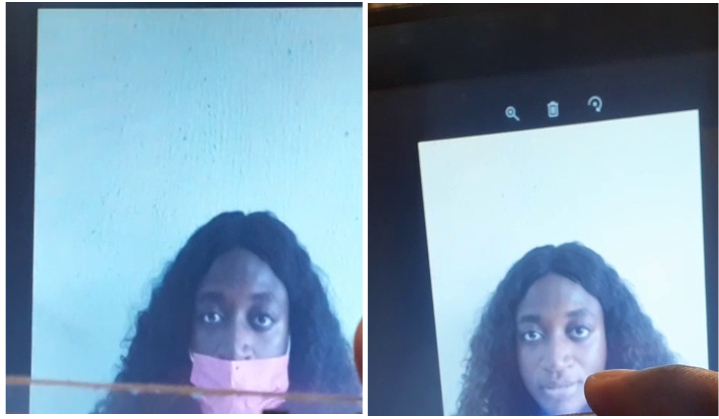
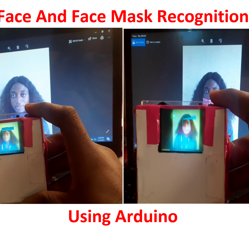
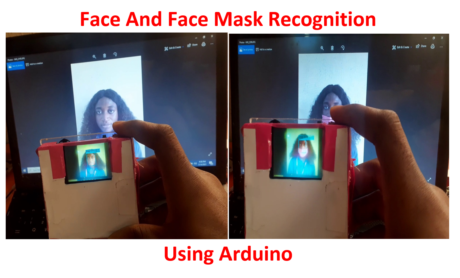
We trained the Huskylenz using images of both people wearing face mask and people not wearing face masks. Like the ones shown here. The more we train under the object recognition and face recognition programs.
Results
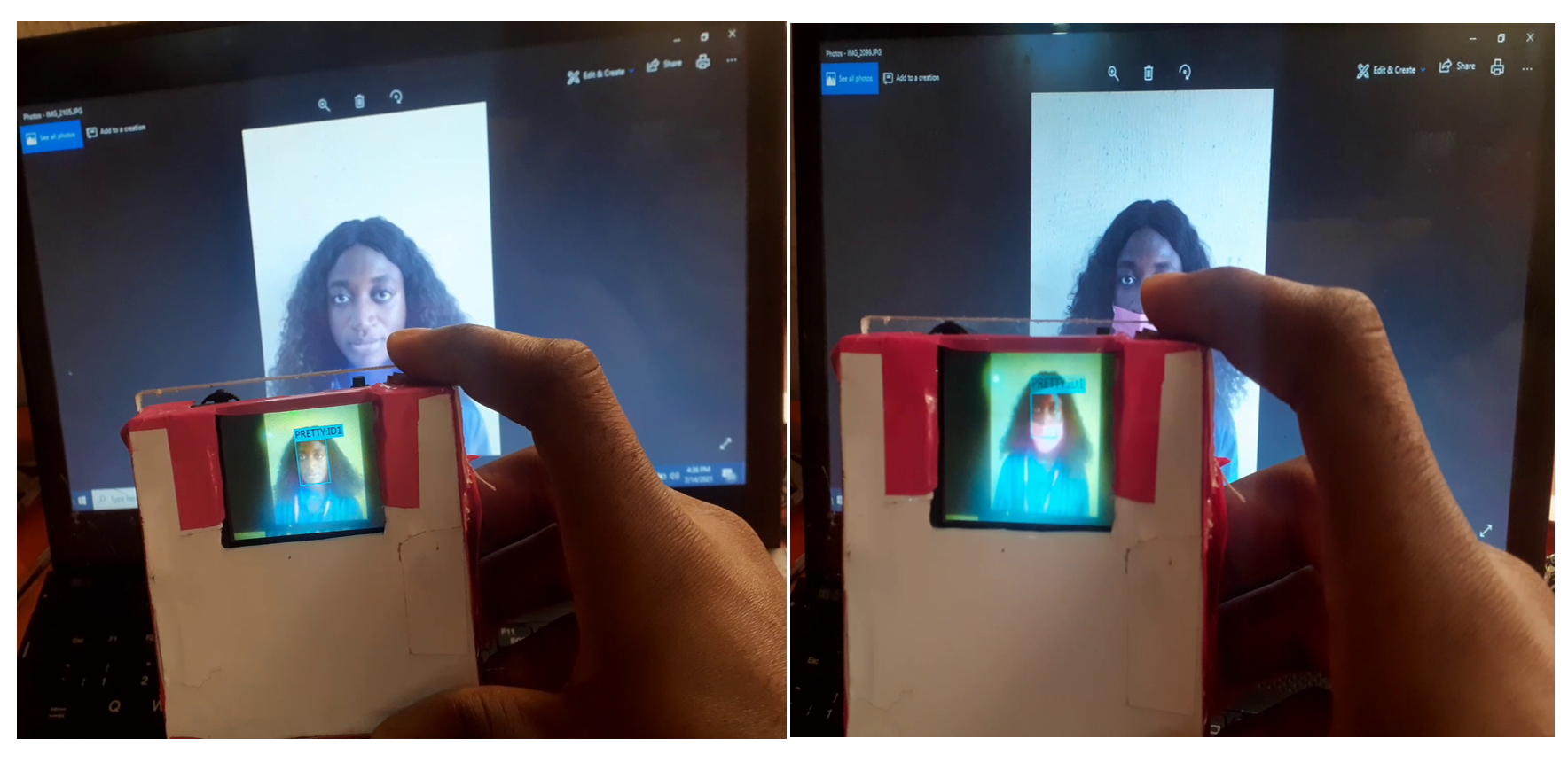
The Arduino Face And Face Mask Recognition project design worked very well in detecting and recognizing the same trained users when they are putting on face mask and when they are not putting on face mask. The system design can used in a place where facial security Identity verification is required and also COVID mask are also mandatory.
Conclusion
The project design has been designed and constructed, programmed and tested and found to be working. Let us know if you have any questions in the comment section below or if you reproduce this project by following the guidelines here step-by-step.

