You can watch the YouTube video demo of the project design above as shown. The schematic diagram and modelling is also shown there.
Introduction
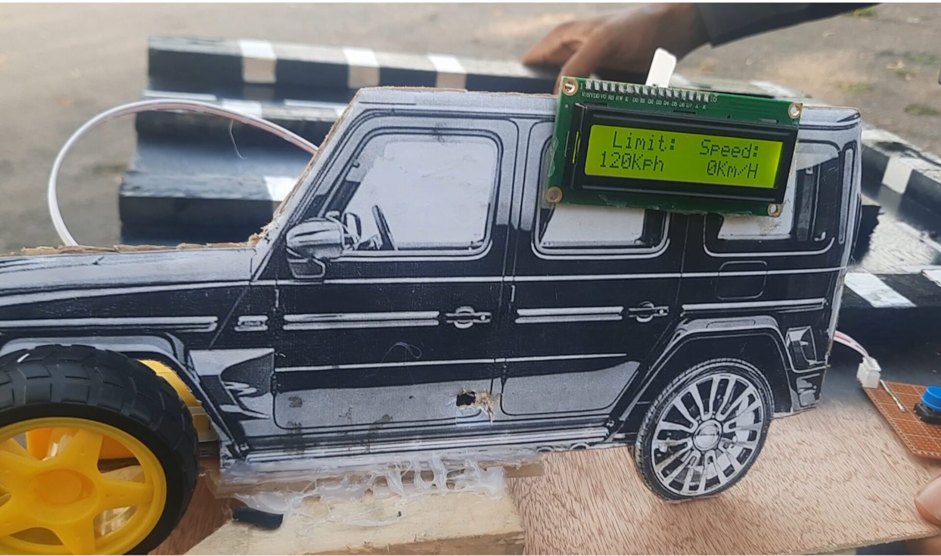
Ever wished there was a system that could limit vehicle speed to improve road safety? Imagine a setup where, regardless of how much you press the accelerator, your vehicle won’t go beyond a preset speed limit. This concept is called “speed limiting” and is increasingly relevant for modern traffic control. In this guide, we’re going to model this idea using Arduino and create a DIY over-speeding limit project that responds to set speed limits.
Let’s dive into the fascinating process of building a mini version of a speed control system. This tutorial will walk you through every component and step you need to complete this project, from setting up the sensors to coding the Arduino Nano.
The Civilization Experienced by Africa During the Early Rise and Development
Project Overview and Objective
What is an Over-Speeding Limit Project?
In real-world applications, speed limiters control how fast a vehicle can go, enhancing safety by limiting top speeds on specific road sections. For this project, we’re building a prototype that allows a model car to self-regulate its speed based on different “zones” where sensors impose limits.
Objective of the Project
Our goal is to create a system that can simulate a car responding to speed limits. When the model car enters a designated area, it will automatically adjust its speed to match the set limit. This project is an excellent exercise in programming, sensor integration, and understanding the fundamentals of speed control.
Required Components and Their Functions
Let’s take a look at the components required to bring this project to life.
Arduino Nano
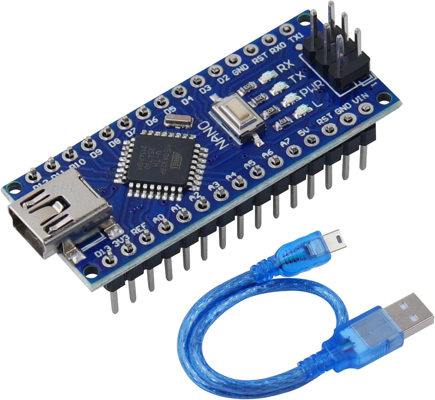
The Arduino Nano serves as the brains of this project. Its compact size and compatibility with the Arduino IDE make it an ideal choice.
Infrared Speed Sensor

This sensor detects the model car’s speed. When the speed exceeds the set threshold, the system will adjust the motor speed accordingly.
Read Also IoT Based Solar Tracker With Weather Station Monitoring With Arduino ESP8266
Motor Driver Module
The motor driver module interfaces between the Arduino and the DC motor, controlling speed and direction based on the Arduino’s signals.
DC Motor

The DC motor simulates the vehicle’s movement, driving the wheels at various speeds based on input from the motor driver.
1602 LCD Module

The LCD module will display the current speed and issue warnings if the vehicle exceeds set limits. It’s an effective way to monitor the system in real time.
Read How to Build an IoT Pulse Rate Monitoring with ESP32 Arduino
Pushbuttons

Pushbuttons act as manual controls for the “driver” to increase or decrease speed, helping to simulate real driving conditions.
Understanding Speed Regulation in This Project
Speed Control Logic

The speed control logic involves using an infrared speed sensor to detect how fast the model car is moving. The Arduino receives this information and decides whether to reduce or maintain speed based on some set speed limts on the modelled road. This project mimics a real-world traffic speed limiter by enforcing preset speed thresholds in specific “zones.”
Simulation of Speed Limit Zones
Imagine a road where each section has different speed limits. This project achieves a similar effect by programming certain thresholds that the car must respect. As the model car moves through these zones, the Arduino makes speed adjustments to keep the car within safe limits.
Read Also Essential marketing strategies for small businesses in 2024
Building the Over-Speeding Limit Project
Let’s go through each step of building this project, from setting up the hardware to uploading code.
Step 1: Set Up the Arduino Nano
Hardware Setup
Start by connecting the Arduino Nano to your computer via USB. Install the Arduino IDE if you haven’t already, and make sure it recognizes the Nano.
The Schematic Diagram

We used the infrared speed sensor in our design to check the number of revolutions hence was able to calculate the speed of the model car.
Step 2: Connect the Infrared Speed Sensor
Placing the Sensor
Position the infrared speed sensor along the path of the model car. It’s essential to place the sensor in a way that can accurately read the wheel’s rotation or another moving part.
Code for Speed Detection
The speed sensor will send readings to the Arduino. Here’s a simple code snippet to read and print speed data:
int speedPin = A0; // Replace with the actual pin for your sensor
float speed;

void setup() {
  Serial.begin(9600);
  pinMode(speedPin, INPUT);
}

void loop() {
  speed = analogRead(speedPin);
  Serial.println(speed);
  delay(100);
}
This code reads speed data, which we can later use to determine whether adjustments are necessary.
Step 3: Integrate the Motor Driver and DC Motor
Connecting the Motor Driver

Connect the motor driver to the Arduino Nano, ensuring the motor driver’s outputs are connected to the DC motor terminals.
Testing the DC Motor
Load a test sketch to check if the motor responds to speed adjustments. Verify that the motor spins at varying speeds depending on Arduino signals.
Step 4: Adding the 1602 LCD Display
Setting Up the Display
Wire the LCD display to the Arduino. Ensure proper connections for SDA, SCL, VCC, and GND.
Over-Speeding Limiter Project Design Arduino Code
The LCD will show the current speed and issue over-speed warnings. Here’s the complete Arduino code.


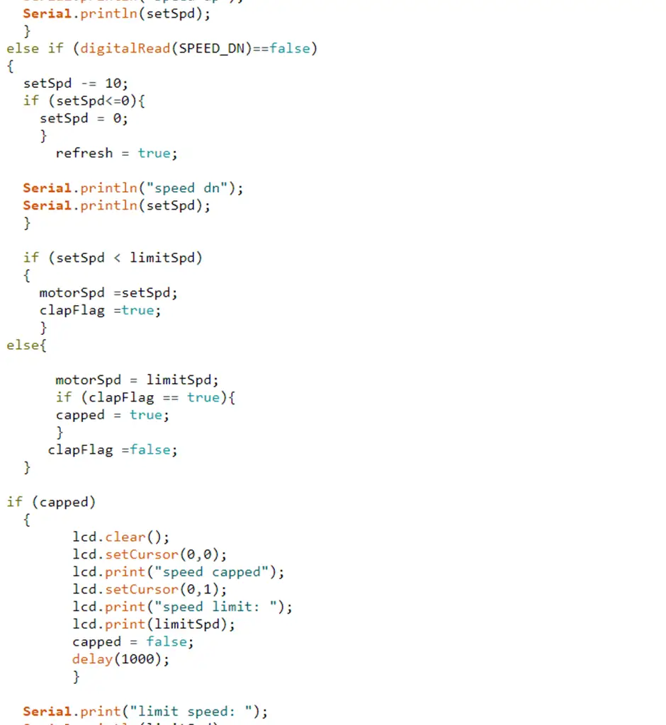

Connecting and Coding Pushbuttons

Connect two pushbuttons to the Arduino. These will simulate the driver’s attempt to accelerate or decelerate. Program the buttons to adjust the car’s speed within a safe range.
Testing and Troubleshooting the Project
Debugging Tips
- Sensor Calibration: If speed readings seem inaccurate, try repositioning the infrared sensor.
- Motor Response: Test the motor independently to rule out power or connection issues.
Testing Scenarios
Simulate different speed zones by programming various speed thresholds and testing the model car’s response as it moves from zone to zone.
Conclusion
This over-speeding limit project demonstrates the power of Arduino in creating practical, real-world systems. Speed regulation is crucial for road safety, and this project simulates how technology can help enforce speed limits. We hope you enjoyed building this model and encourage you to experiment further—perhaps by adding new speed zones or exploring other sensors. Happy building!
Call to Action
Did you enjoy this project? Let us know in the comments below! For more Arduino ideas, check out our other tutorials and join our community of makers.
FAQs Arduino Over-speeding Limit Project Design
1. How does the over-speeding control work in this project?
The infrared sensor detects speed, and if it surpasses set limits, the Arduino adjusts the motor speed to keep it within safe thresholds.
2. Can I use a different Arduino model?
Yes, other models like the Arduino Uno can work, though you might need to adjust some wiring and code.
3. Is the LCD display necessary?
The LCD display is optional but recommended for real-time feedback on speed and warnings.
4. What power source should I use?
You can use a 9V battery or USB power, but ensure it matches the motor’s requirements for smooth operation.
5. How do I simulate multiple speed zones?
Use conditional statements in the code to trigger specific speed limits based on data from the infrared sensor.
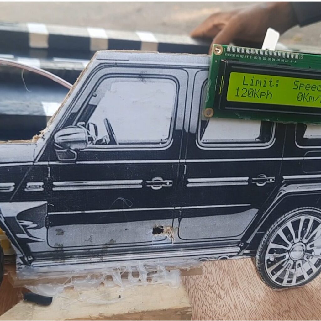

WOULD LIKE TO BUILD A UNIT THAT WOULD MEASURE CAR SPEED AND HIGHLIGHT WHEN OVER SPEED LIMIT