This is a smart build design that involves the construction and assembly of a 3-phase distribution panel at Smartech Labs. This is industrial distribution panel that can be used to safely control the actuators and AC loads in a production facility. This blog post is a step-by-step guide; we will take you through all the processes involved in the making of the 3-phase distribution panel. The right component ratings were critical for everything from component selection to the type of box chosen, the dimensions of the holes drilled, the openings cut out to fit components on the box, etc. IF you want this design, kindly fill out the form below.
It’s a distribution panel with 7 outgoing sub-circuits. Three (3) numbers of single phase outlets. Four (4) numbers of 3-phase outlets. Each outlet is isolated by an MCB. Two (2) pole MCB for the single phase outlets. Four (4) pole MCB for the 3-phase outlets. The input isolator is an MCCB from which all the sub- circuit isolators are supplied.

Component Selection and Identification
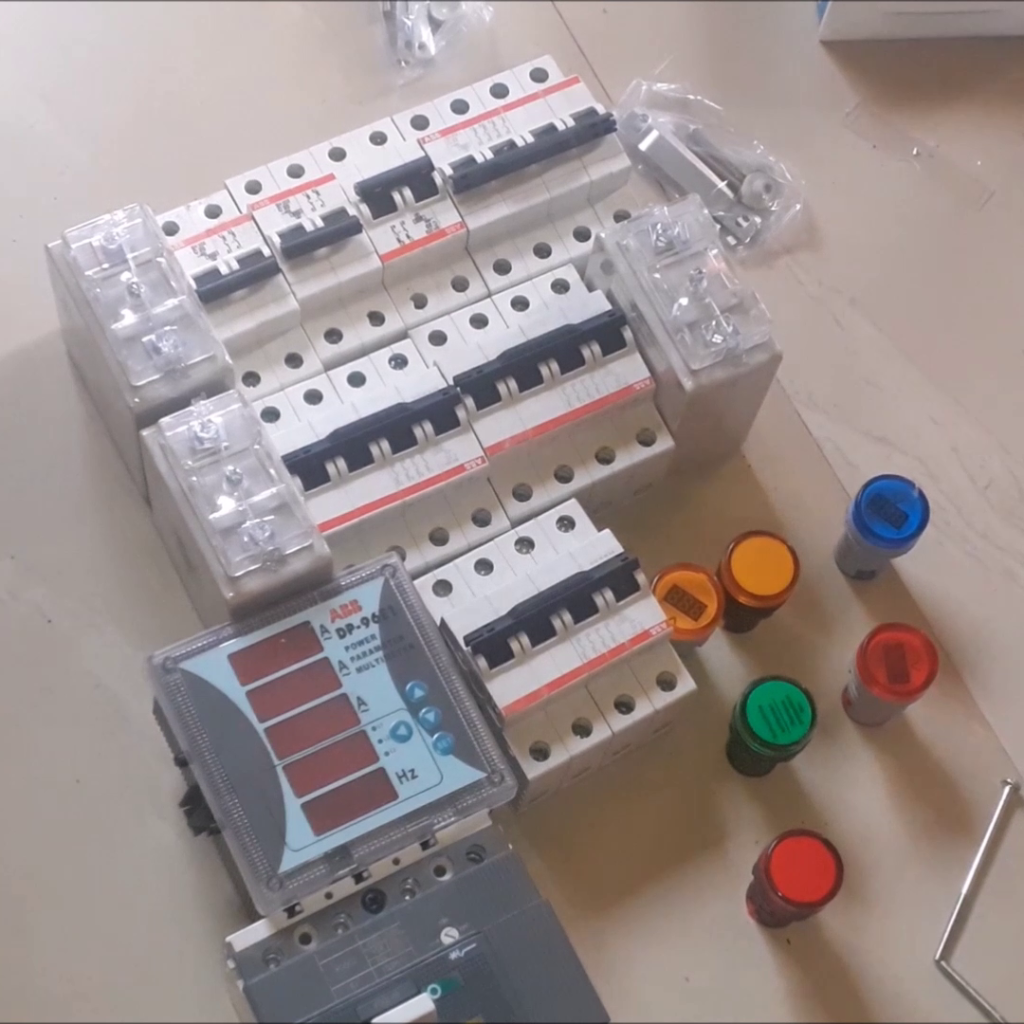
The components used in this design were acquired based on the list below. Their functions are very vital to the needs of the 3-phase distribution panel design.
- Panel Box H=600mm x W=400mm x H=200mm….1 pieces
- Moulded Case Circuit Breaker (MCCB) 100A….1 pieces
- 4 pole Miniature Circuit Breaker (MCB)….4 pieces
- 2 pole MCB….3 pieces
- 1 pole MCB
- Flat copper bars 200A….4 pieces
- Current transformer….3 pieces
- Power Cable 10mm 4 core….25 yards
- Control wire 1.5mm….20 yards
- Link wire 6mm….
- Pilot Lamps…….3 Pieces
- Lamp meter….. 3 pieces
- Cable lugs……. 6 pieces
- Bolts, Washer and nuts….
- Insulation bus bar (angle bar)
- Insulation tape
The Schematic Diagram

This is a commercial product that is being designed and built in Smartech Lab. If you would like a copy of the schematic diagram, please order one from any of the social media platforms listed below.
Step 1:
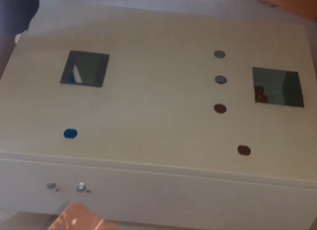
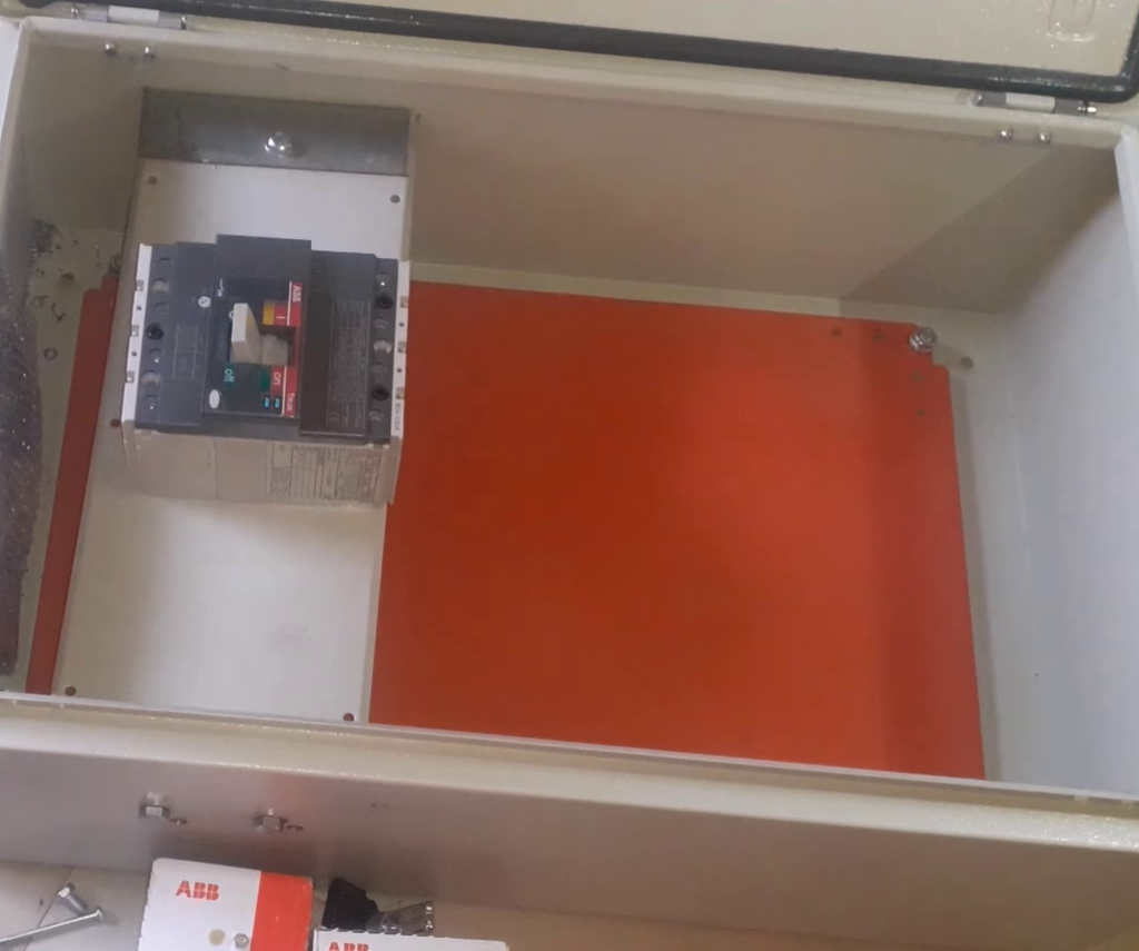
Selecting the appropriate box size and dimension. The 3-phase distribution panel built here used a box dimension of H=600mm x W=400mm x H=200mm. The components needed to be protected from dust and moisture. A suitable box with the right openings to house the load controls must be selected. The box must be big enough to contain all the components needed for the build design. As shown below, this box has a two bases at which components like breakers are placed strategically. As such, even when the lid is closed, the the openings were made to bring out the switch MCCB button.
Step 2:
Having an idea of how the design would turn out to look at the finished stage is very important. The arrangement of the components inside the box, and how they will be presented to the used or maintenance team when they open it is also very important.
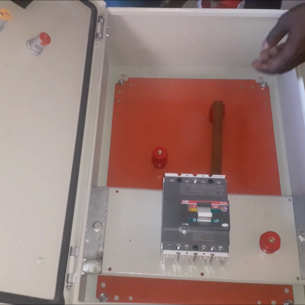
Setting the components at the right orientation and alignments in the box. The box size may seem big enough to contain all the components but without tinkering and deciding where each control of the 3-phase distribution panel would be placed, the whole design will become quite cumbersome when it comes in routing of wires. Hence the components have to be mapped out at stratetic positions, the ease of running wires through them ascertained and ensuring that the box closes after it is all done.
Construction of the Distribution Panel Design
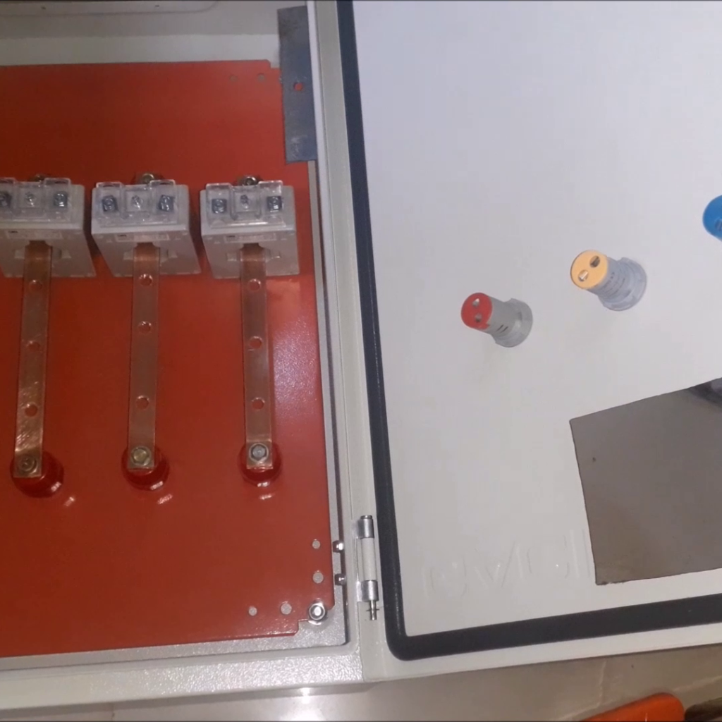
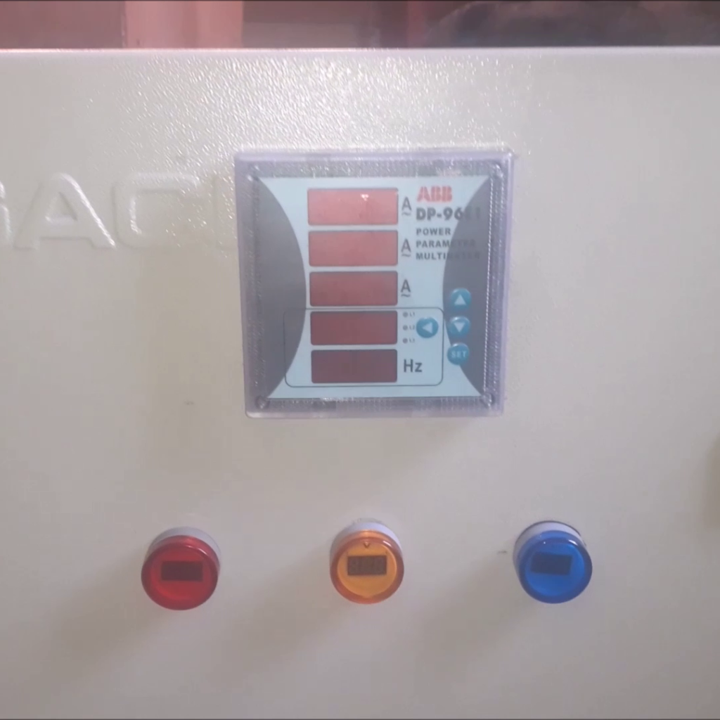
To get started on the construction, the base setting was used. Insulation bus bars and copper flat bars were used to make the termination and foundation points for connections. These were laid out perfectly and according to plan to ensure easy connections and termination of wires. The current transformers were used to do load balancing on each phase, hence the placement on each copper bar. The 3-phase voltmeter indicators were also mounted on the box lid. They came in the colors of red, green, and yellow.
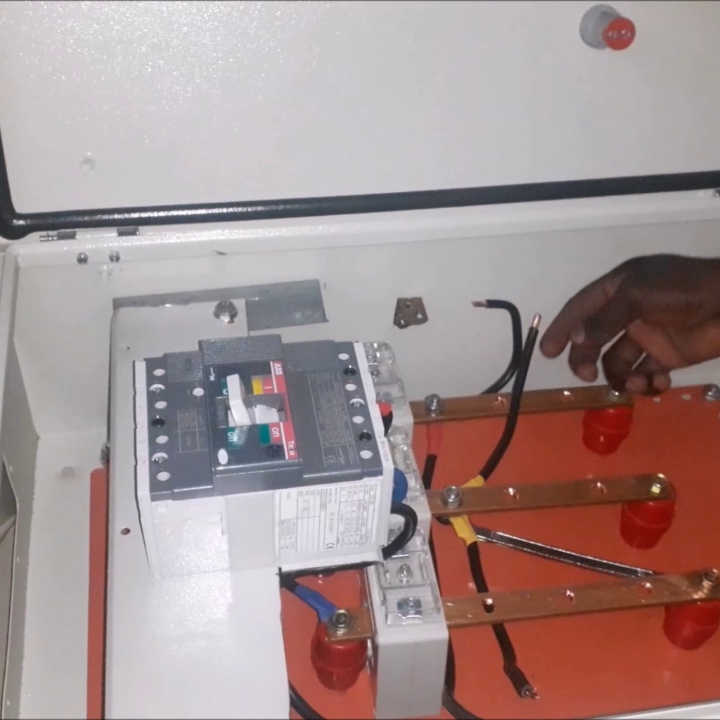
These indicator voltmeters were also made to read the various voltages of the phase they were connected to. The MCCB (main breaker switch) is connected first, terminating its cable on the copper flat bar below it. This switch controls everything on this distribution. Once it is flipped on, the distribution is activated.
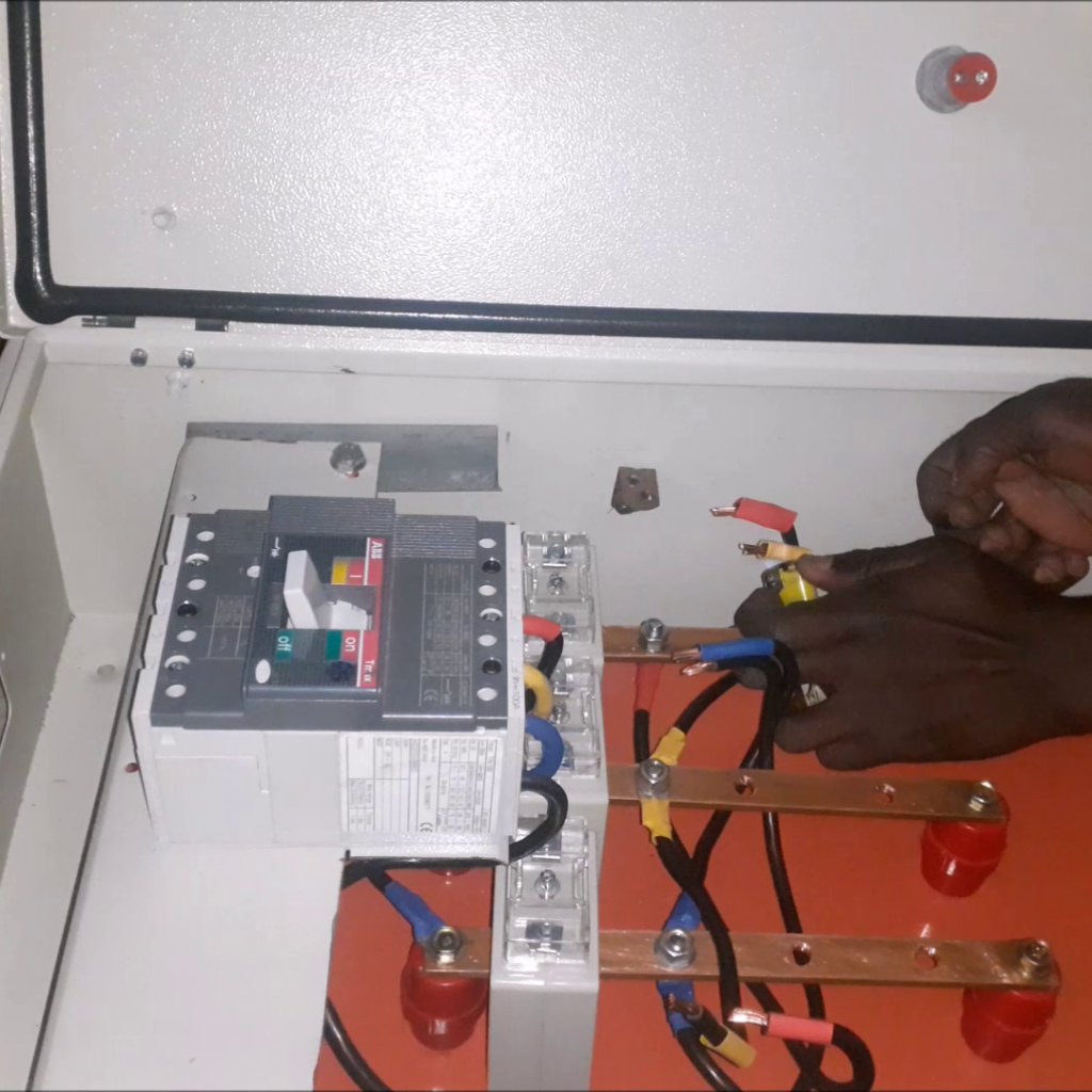
Properly lugged cables were used to make firm connections to this breaker. We used the other 3-phase breaker as shown in the schematic diagram. The breakers were finally brought in on a DIN rail. Next, is to wire the controls. This was neatly done and the indicator voltmeters were connected.
Conclusion
As shown, the design is fully assembled and ready to be installed at the facility of choice. It is fully automated, and easy to use. It is also sleek and well presentable; giving both an efficient and robust design feel. And this is how we designed the 3-phase distribution panel design that can be used in any factory or facility to ensure proper load balancing. Let us us know if you have any questions or if you
would want to order one from us
Read More
Japan introduces delivery robots that are humble and friendly.
See How Four-legged Robots Run Efficiently in the Wild, Thanks to Improved Algorithms