In today’s world, livestock farming is a critical sector that drives food production. However, managing livestock health and safety can be challenging, especially with large herds scattered across vast areas. Traditional methods for monitoring livestock can be inefficient and costly, which is why technology offers an innovative solution. With advancements in microcontrollers and IoT, it is now possible to track livestock using smart devices. In this post, we explore a project that utilizes Arduino, LoRa, GPS, and sensors to create a comprehensive livestock tracking system. This system not only monitors location but also keeps track of the animal’s health, sending real-time alerts to the owner.
What Is a Smart Livestock Tracking System?
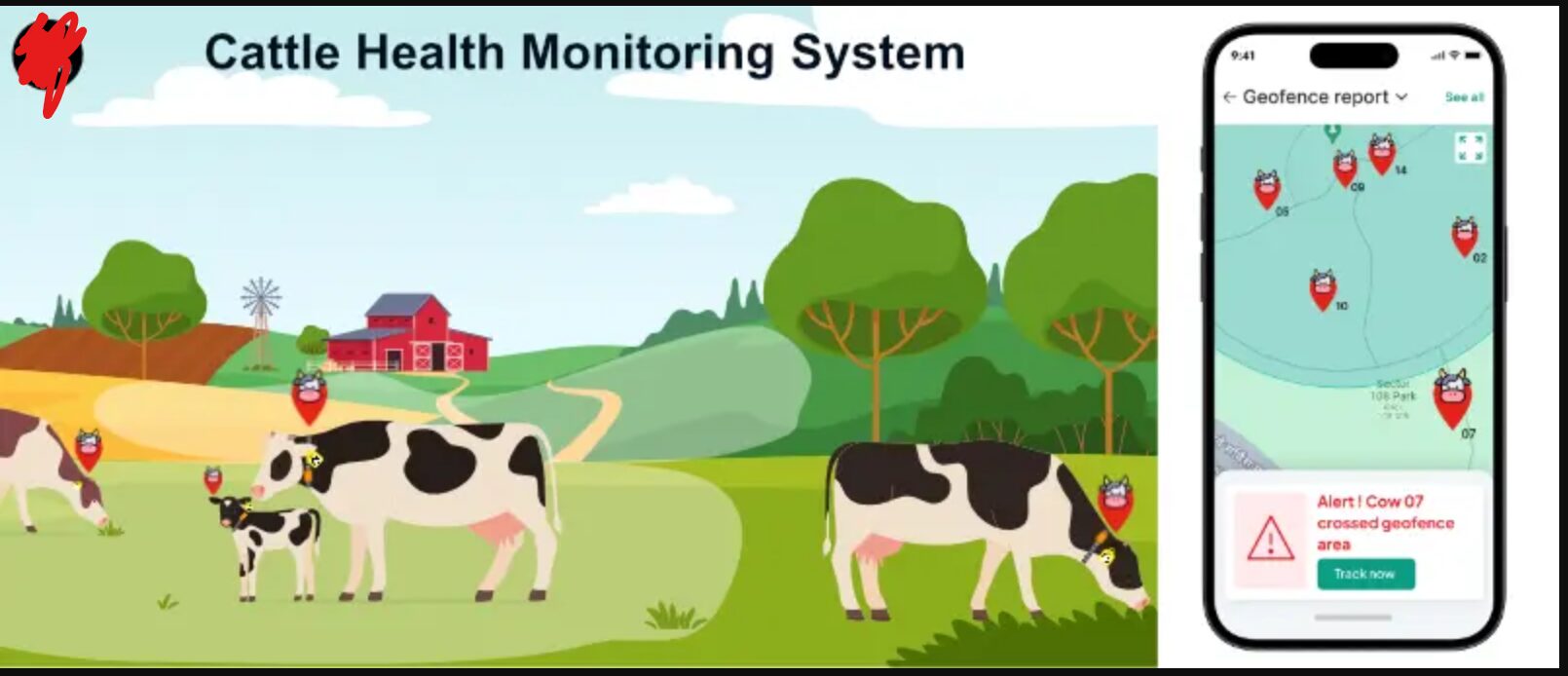
A smart livestock tracking system integrates various sensors and communication modules to provide real-time information about livestock, including their location, health parameters, and environmental conditions. The system discussed in this bpost uses Arduino Nano, LoRa modules, GPS, and GSM technology, along with sensors like DHT11 (for temperature and humidity) and a pulse rate sensor.
The system collects data from these sensors, processes it, and sends alerts via SMS if the animal’s health conditions become abnormal. The information is also transmitted via LoRa technology to a receiver that displays it on an LCD screen, making it easier for farmers to monitor their livestock remotely.
Read Also 10 Shocking Facts About Alcohol You Didn’t Know (But Should)
Components/Modules for Livestock Tracking Project Design
To build this livestock tracker, we utilized several essential components, each contributing to the system’s functionality. Let’s break down each of these:
Arduino Nano
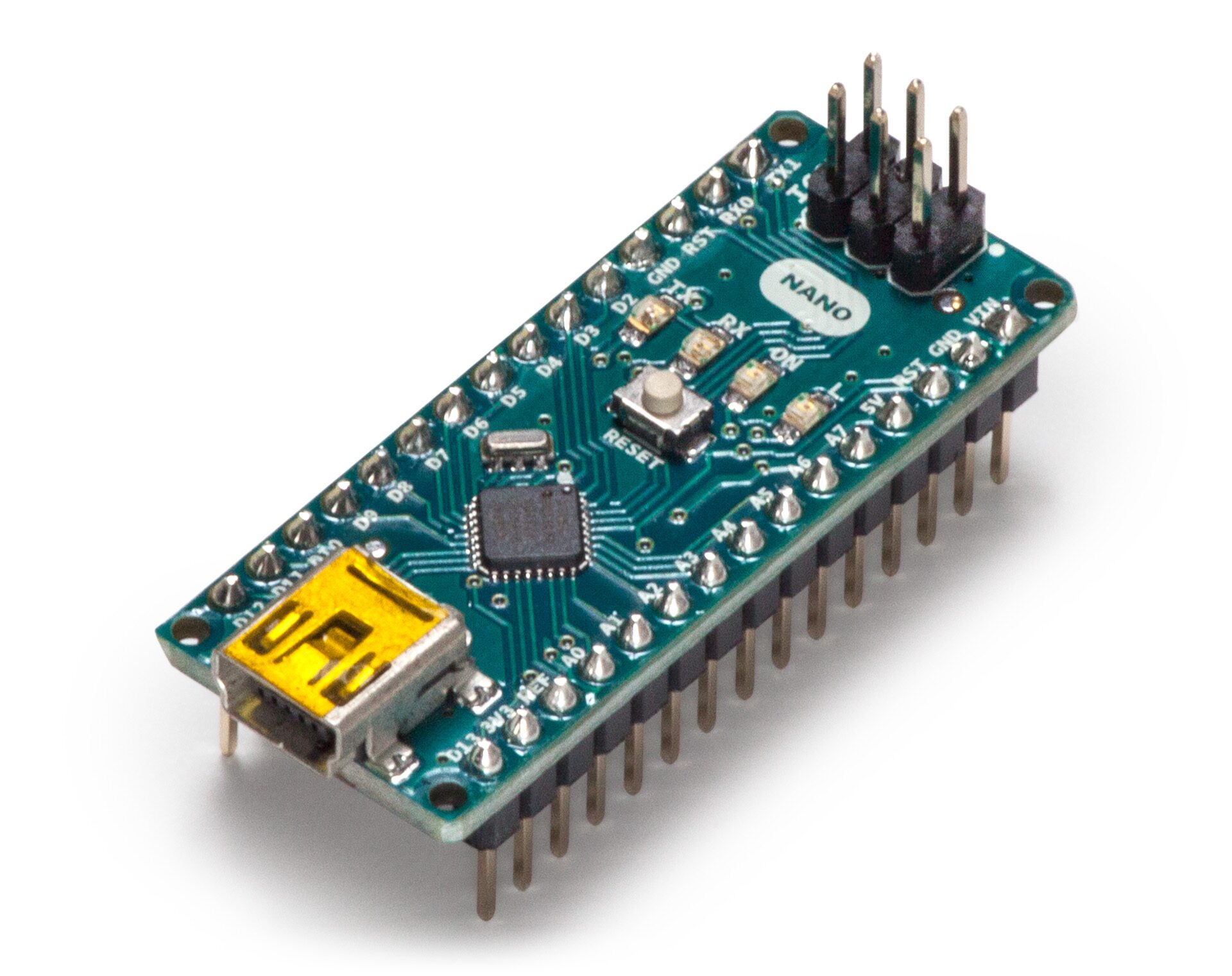
The Arduino Nano is the core microcontroller that runs the entire system. It processes data from the sensors and controls communication between the GPS, GSM, and LoRa modules. Due to its compact size and low power consumption, the Nano is ideal for this application.
Read Also How to Build An Automatic Toilet Flusher with Arduino
Neo-6M GPS Module
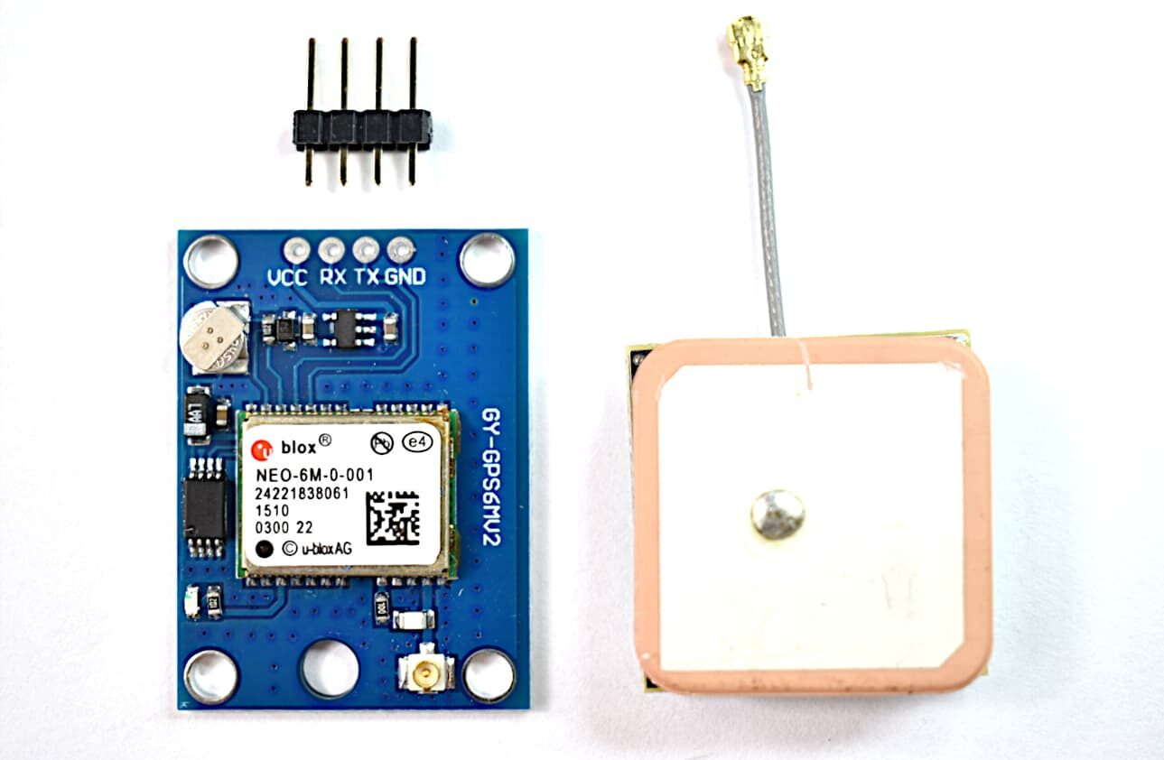
The Neo-6M GPS module provides accurate geolocation data. In this system, the GPS module tracks the livestock’s location in terms of latitude and longitude, which is sent to the owner via SMS. GPS tracking is crucial for preventing livestock theft or tracking animals that have wandered off.
LoRa 433MHz Modules
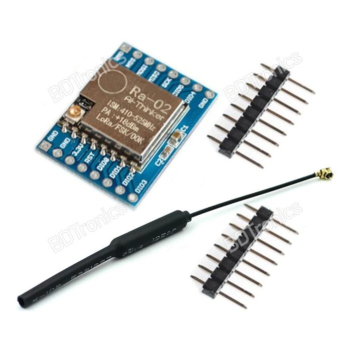
LoRa (Long Range) modules enable wireless communication between the transmitter (on the livestock) and the receiver (with the farmer). The 433MHz LoRa modules have a range of up to 10 km, making them perfect for transmitting data across large farms.
SIM800 EVB GSM Module
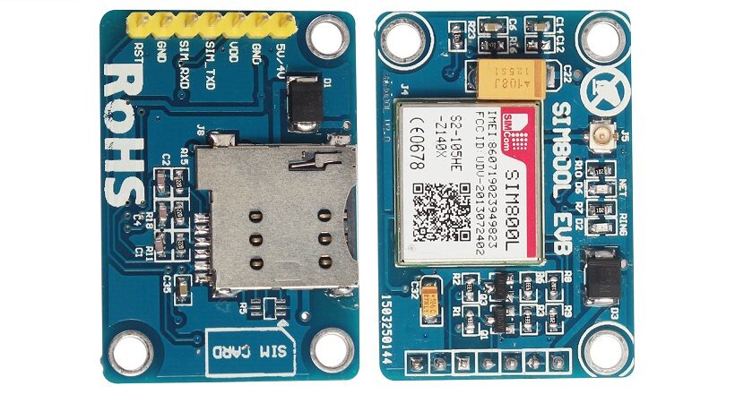
The SIM800 EVB GSM module sends SMS alerts with the GPS location and health status of the livestock. It provides the farmer with real-time updates through text messages, including Google Maps links with the animal’s exact location.
DHT11 Sensor
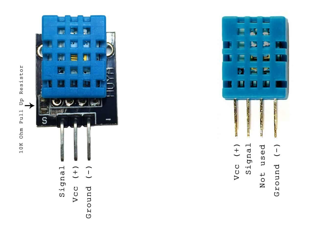
The DHT11 sensor measures both temperature and humidity. This sensor monitors the livestock’s environmental conditions, ensuring that animals are not exposed to extreme temperatures or humidity levels that could affect their health.
Pulse Rate Sensor
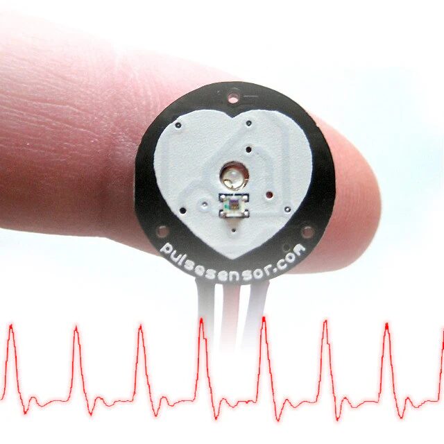
The pulse rate sensor is designed to measure the animal’s heart rate. Abnormal pulse rates can be an indication of stress or illness, and this data is crucial for early intervention.
3.7V LiPo Rechargeable Battery
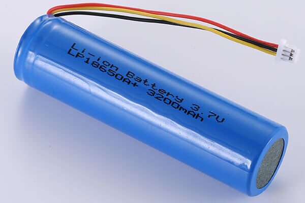
A 3.7V LiPo battery powers the entire system, making it portable and easy to attach to the animal’s collar or harness.
Piezo Buzzer
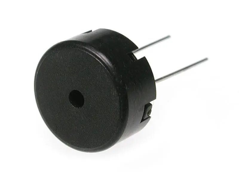
A piezo buzzer attached to the receiver alerts the farmer when an abnormal reading is detected. This provides an additional layer of notification beyond the SMS alerts.
Read Also IoT Health Monitoring with LoRa, ESP32 Arduino for Real-Time Tracking
How the Livestock Tracking System Works
The system is designed to be both efficient and practical. Here’s how it works, from powering on to sending real-time alerts:
Powering the Transmitter
Once the transmitter side of the system, which is attached to the livestock, is powered on using the rechargeable LiPo battery, the GSM module automatically connects to the network.
Location Tracking via GPS
The GPS module kicks in and starts gathering the current location of the animal. The data it collects includes latitude and longitude, which are crucial for tracking the animal in real-time. This data is sent periodically to the GSM module.
Health Monitoring with DHT11 and Pulse Rate Sensor
The DHT11 sensor continuously measures the temperature and humidity surrounding the animal. Simultaneously, the pulse rate sensor monitors the animal’s heart rate. These sensors ensure the animal’s environment and health are within safe limits.
Data Transmission via LoRa
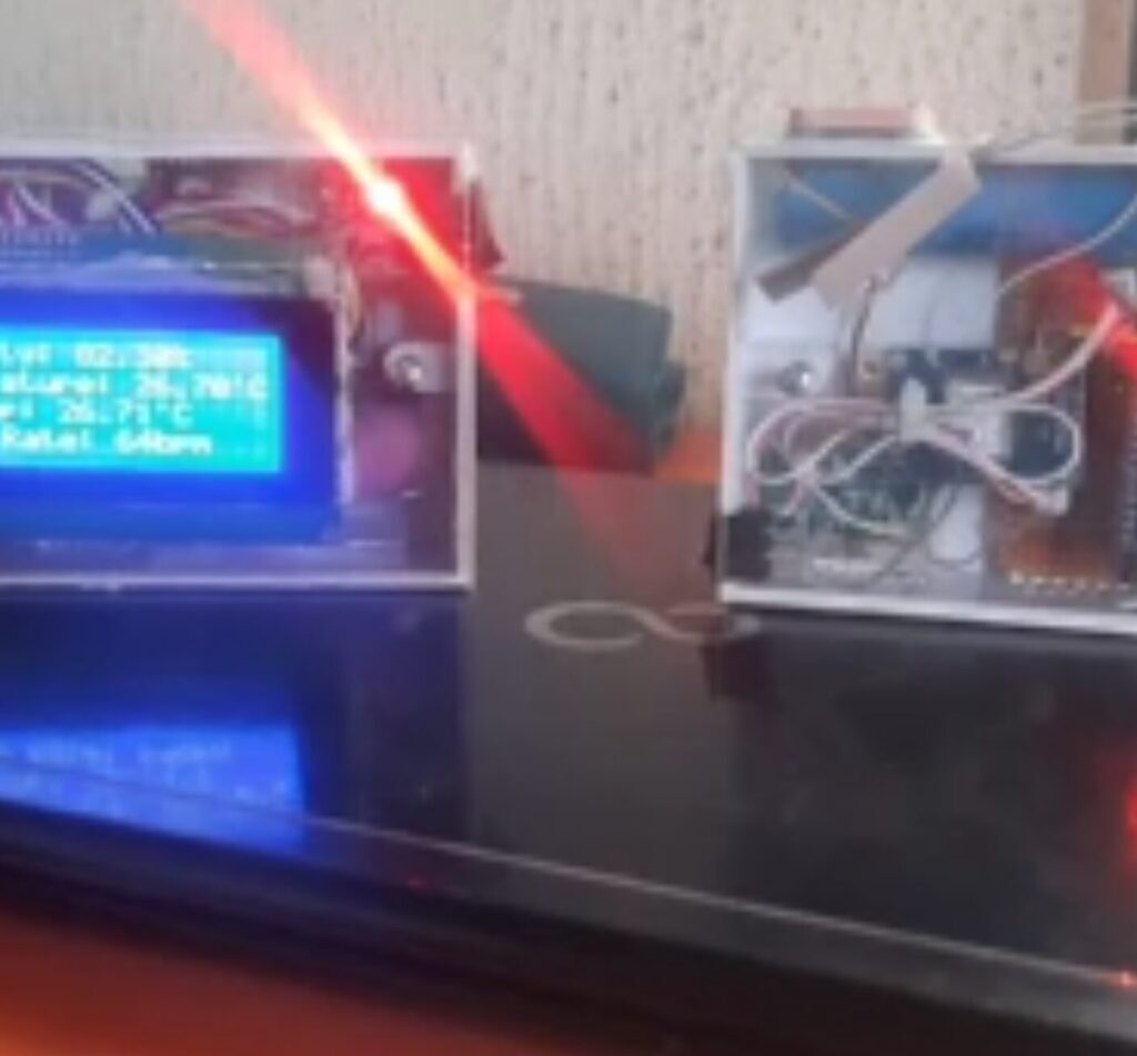
When the sensors detect normal conditions, the data (location, temperature, humidity, and pulse rate) is sent via the LoRa module to the receiver. The receiver displays this information on a 20×4 LCD screen, allowing the farmer to monitor the data in real-time.
Abnormal Condition Alerts
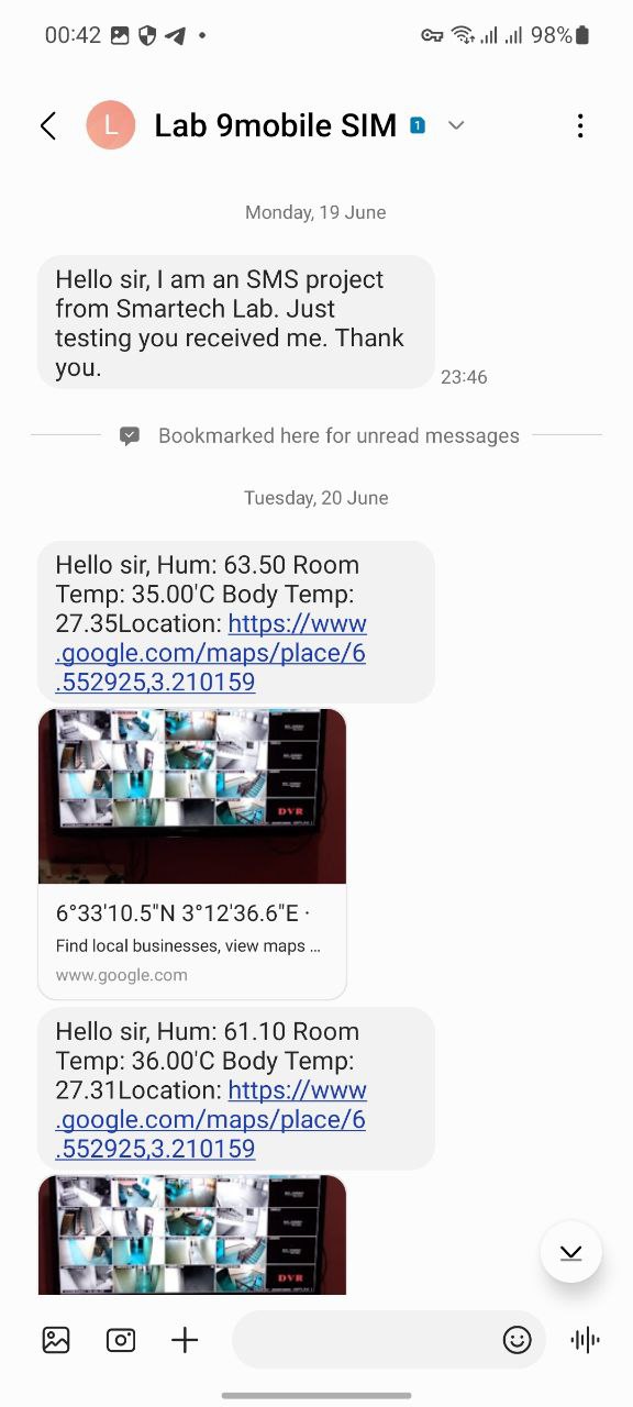
If any of the sensors detect abnormal conditions, such as extreme temperatures, high humidity, or an irregular pulse rate, an alert is triggered. The GSM module immediately sends an SMS to the owner, which includes the current GPS location of the animal in the form of a Google Maps link, along with details about the abnormal condition.
Simultaneously, the LoRa module transmits the alert to the receiver, where a piezo buzzer sounds to indicate that something is wrong. The farmer can then take immediate action to check on the livestock.
Read Also Arduino Laser-Based Intrusion Detection System: Anti-Burglar with GSM Control
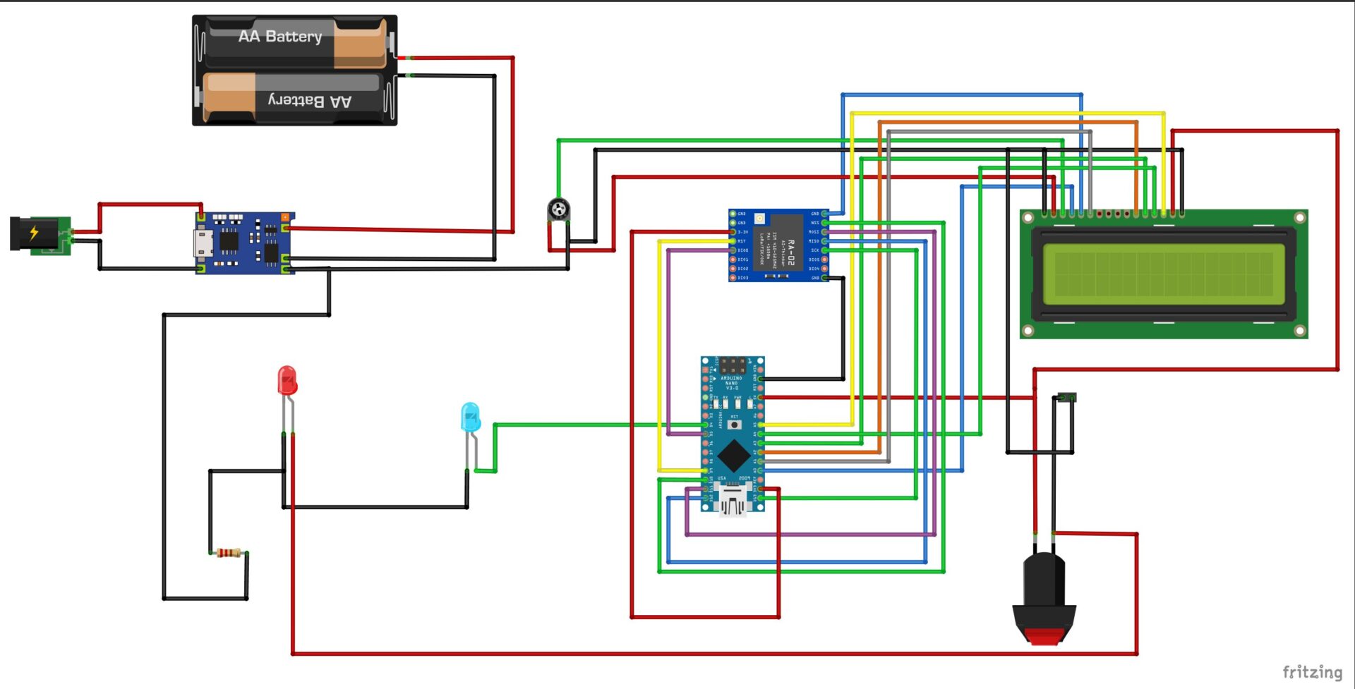
The Schematic Diagram
The Transmitter Side
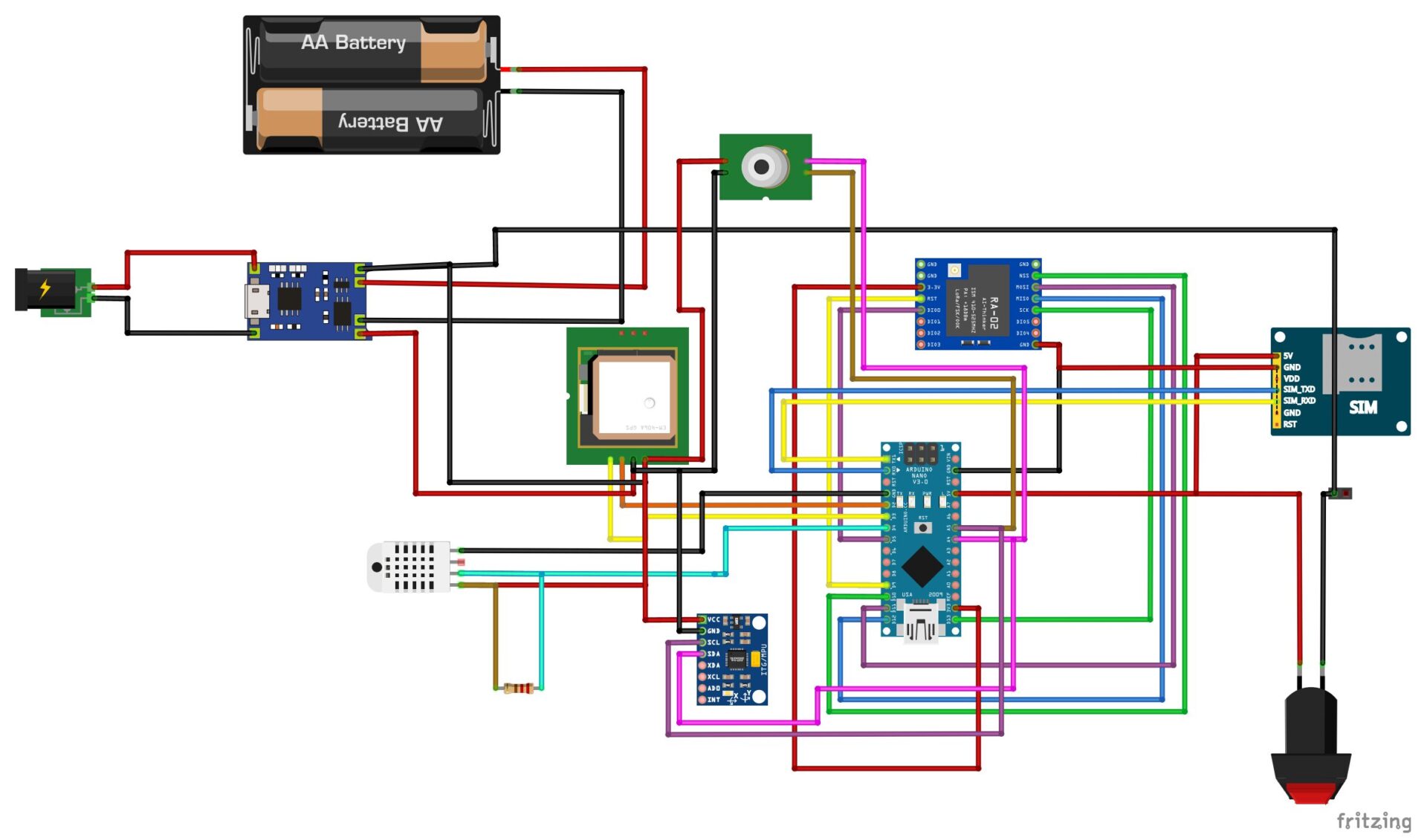
The schematic diagram shown above shows the connection of the various sensors and modules connected to the Arduino Nano board. The GPS module is connected via serial communication with the Arduino Nano. And the GSM module connected via hardware serial communication.
Explanation of The Smart Livestock Tracker Schematic Diagram (The Transmitter Side)
We added the non-contact temperature sensor module MLX90614 to the mix to be able to take the body temperature of the livestock. This sensor works on 3.3V so we connected it to the 3.3V voltage output power rail on the Arduino Nano board.
The DHT11 sensor was used to measure the surrounding temperature and humidity around the livestock itself and since we were using the sensor version of DHT11, we added a 10k resistor between the Digital output pin of the sensor and the power pin. The system was power by a rechargeable battery and we included a charging port for this. Also, the module allowed us to take a 5V from the 3.7V battery.
The Receiver Side
Explanation of The Smart Livestock Tracker Schematic Diagram (The Receiver Side)
We used the LCD to display what the transmitter side is seeing and measuring. And the setup above shows that we also used a rechargeable battery to make the system energy sustainable too. The LoRa module receives the messages sent by the transmitter and the LCD displays it.
Read Also How to Apologize to Your Boyfriend Without Saying ‘Sorry’
Assembling The Smart Livestock Tracker Project Design: A Step-by-Step Guide
Now that we’ve discussed the components and how the system works, let’s walk through the setup process:
Assembling the Transmitter
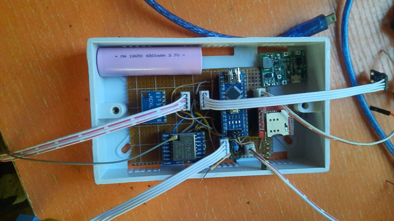
- Begin by connecting the Neo-6M GPS module, DHT11 sensor, pulse rate sensor, LoRa module, and SIM800 GSM module to the Arduino Nano on the transmitter side.
- Ensure that the LiPo battery is properly connected to provide a steady power supply.
Setting Up the Receiver
- On the receiver side, connect the LoRa module and LCD screen to the Arduino Nano.
- Attach a piezo buzzer to sound an alert or add two LED indicators, a green LED blinks to show normal conditions and a Red LED that blinks when abnormal conditions are detected.
Programming the Arduino
The Arduino Transmitter Code
#include <SPI.h>
#include <LoRa.h>
#include "DHT.h"
#include <Adafruit_MLX90614.h>
#include <TinyGPS++.h>
#include <SoftwareSerial.h>
#include <SerialGSM.h>

// Choose two Arduino pins to use for software serial
int RXPin = 3;
int TXPin = 4;

int GPSBaud = 9600;
// Create a TinyGPS++ object
TinyGPSPlus gps;

String latitude = "";
String longitude = "";
String message = "";

// Create a software serial port called "gpsSerial"
SoftwareSerial gpsSerial(RXPin, TXPin);

Adafruit_MLX90614 mlx = Adafruit_MLX90614();

// Digital pin connected to the DHT sensor
#define DHTPIN 5

String SMS;

int counter, sensorPin = 0;
bool panic;
float h, t, f, animalBodyTemp;
int sensorAnalog,heartRate, checkHBP, checkLBP = 0;
String greeting = "hello";


 // DHT 11
#define DHTTYPE DHT11
// as the current DHT reading algorithm adjusts itself to work on faster procs.
DHT dht(DHTPIN, DHTTYPE);

void loraSetup(){
    while (!Serial);
  Serial.println("LoRa Sender");

  //replace the LoRa.begin(---E-) argument with your location's frequency
  //433E6 for Africa & Asia
  //866E6 for Europe
  //915E6 for North America
  while (!LoRa.begin(433E6)) {
    Serial.println(".");
    delay(500);
  }
   // Change sync word (0xF4) to match the receiver
  // The sync word assures you don't get LoRa messages from other LoRa transceivers
  // ranges from 0-0xFF
  LoRa.setSyncWord(0xF4);
  Serial.println("LoRa Initializing OK!");
}

void setup() {
//initialize Serial Monitor
  Serial.begin(9600);
//begin the dht sensor
 dht.begin();
//start the LoRa setup
loraSetup();
if (!mlx.begin()) {
    Serial.println("Error connecting to MLX sensor. Check wiring.");
    while (1);
  }
  // Start the software serial port at the GPS's default baud
  gpsSerial.begin(GPSBaud);
//set ur inputs and outouts make the buzzer an output
// pinMode(buzzerPin, OUTPUT);
//pinMode(HBPpin, INPUT_PULLUP);
//pinMode(LBPpin, INPUT_PULLUP);

}

float dhtSensor(){
  // Reading temperature or humidity takes about 250 milliseconds!
  // Sensor readings may also be up to 2 seconds 'old' (its a very slow sensor)
   h = dht.readHumidity();
  // Read temperature as Celsius (the default)
   t = dht.readTemperature();
  // Read temperature as Fahrenheit (isFahrenheit = true)
   f = dht.readTemperature(true);
return h, t, f;
  // Check if any reads failed and exit early (to try again).
  if (isnan(h) || isnan(t) || isnan(f)) {
    Serial.println(F("Failed to read from DHT sensor!"));
  }

  // Compute heat index in Fahrenheit (the default)
  float hif = dht.computeHeatIndex(f, h);
  // Compute heat index in Celsius (isFahreheit = false)
  float hic = dht.computeHeatIndex(t, h, false);
}

float mlxTempSensor(){
  animalBodyTemp = mlx.readObjectTempC();
  return animalBodyTemp;
}

int pulseSensor(){
sensorPin = analogRead(A3);
sensorPin = map(sensorPin, 1, 1023, 0, 100);
sensorPin = constrain(sensorPin, 1, 100);
return sensorPin;
}

String displayInfo(){
  if (gps.location.isValid()){
    latitude = String(gps.location.lat(), 6);
    longitude = String(gps.location.lng(), 6);
        //message = "";
    message = "https://www.google.com/maps/place/" + String(gps.location.lat(), 6) + "," + String(gps.location.lng(), 6);

  }
  else{
    Serial.println("Location: Not Available");
  }

  Serial.print("Date: ");
  if (gps.date.isValid()){
    Serial.print(gps.date.month());
    Serial.print("/");
    Serial.print(gps.date.day());
    Serial.print("/");
    Serial.println(gps.date.year());
  }
  else{
    Serial.println("Not Available");
  }

  Serial.print("Time: ");
  if (gps.time.isValid()){
    if (gps.time.hour() < 10) Serial.print(F("0"));
    Serial.print(gps.time.hour());
    Serial.print(":");
    if (gps.time.minute() < 10) Serial.print(F("0"));
    Serial.print(gps.time.minute());
    Serial.print(":");
    if (gps.time.second() < 10) Serial.print(F("0"));
    Serial.print(gps.time.second());
    Serial.print(".");
    if (gps.time.centisecond() < 10) Serial.print(F("0"));
    Serial.println(gps.time.centisecond());
  }

  else{
    Serial.println("Not Available");
  }
  Serial.println();
  delay(1000);
  return latitude, longitude, message;
}

void checkGPS(){
// This sketch displays information every time a new sentence is correctly encoded.
  while (gpsSerial.available() > 0)
    if (gps.encode(gpsSerial.read()))
      displayInfo();

  // If 5000 milliseconds pass and there are no characters coming in
  // over the software serial port, show a "No GPS detected" error
  if (millis() > 5000 && gps.charsProcessed() < 10){
    Serial.println("No GPS detected");
    while(true);
  }
}

void sendSMS(){
 dhtSensor();
 mlxTempSensor();
 checkGPS();
 if((t >= 34.80) || (animalBodyTemp >= 40.00) ){
   Serial.println("AT"); //Once the handshake test is successful, it will back to OK
  updateSerial();
  Serial.println("AT+CMGF=1"); // Configuring TEXT mode
  updateSerial();
  Serial.println("AT+CMGS=\"+2348062020050\"\r\n");//change ZZ with country code and xxxxxxxxxxx with phone number to sms
  updateSerial();
  Serial.print("Hello sir, Hum: " + String(h) + " Room Temp: " + String(t) + "'C " + "Body Temp: " + String(animalBodyTemp)+ "Location: " + message); //text content
  updateSerial();
  Serial.write(26);
  delay(5000);
  sendSMS1();
 }

 else{
Serial.println("All good") ;
 }

}

void sendSMS1(){
    Serial.println("AT"); //Once the handshake test is successful, it will back to OK
  updateSerial();
  Serial.println("AT+CMGF=1"); // Configuring TEXT mode
  updateSerial();
  Serial.println("AT+CMGS=\"+2348103131467\"\r\n");//change ZZ with country code and xxxxxxxxxxx with phone number to sms
  updateSerial();
  Serial.print("Hello sir, Hum: " + String(h) + " Room Temp: " + String(t) + "'C " + "Body Temp: " + String(animalBodyTemp)+ "Location: " + message); //text content
  updateSerial();
  Serial.write(26);
 }


void sendTruLoRa(){
    sendSMS();
    pulseSensor();

  Serial.println("<<<Sending packet>>>");
  Serial.print("hum: ");Serial.print(h);
  Serial.print(" temp: "); Serial.print(t);
  Serial.print(" Animal B.Temp: ");
  Serial.print(animalBodyTemp);
  Serial.print(" Pulse Rate: ");
  Serial.println(sensorPin);
  Serial.print(" GSP coordinates: ");
  Serial.println(message);
  delay(1000);

  //Send LoRa packet to receiver
  LoRa.beginPacket();
  //use delimiters
  LoRa.print('<');
  LoRa.print(greeting); LoRa.print(',');
  LoRa.print(h);LoRa.print(',');
  LoRa.print(t);LoRa.print(',');
  LoRa.print(animalBodyTemp);LoRa.print(',');
  LoRa.print(sensorPin);
  LoRa.print('>');
  LoRa.endPacket();

}

void loop() {
  sendTruLoRa();

}

void updateSerial(){
  delay(500);
  while (Serial.available()) {
    Serial.print(Serial.read());//Forward what Serial received to Software Serial Port
  }
  while(Serial.available())
  {
    Serial.write(Serial.read());//Forward what Software Serial received to Serial Port
  }
}
Explanation of The Arduino Code
The code utilizes various sensors to gather information. It reads humidity and temperature using a DHT sensor, detects animal body temperature with an MLX sensor, and retrieves GPS coordinates through a software serial connection. Additionally, it seems to have provisions (though not actively used) for reading pulse rate and monitoring high/low blood pressure (sensors not included in the provided code).
The code transmits collected data (humidity, temperature, animal body temperature, pulse rate – if implemented, and GPS coordinates) via LoRa technology. It also checks for specific conditions, like high room temperature or animal body temperature. If these thresholds are exceeded, the code sends SMS alerts with the sensor readings and location information to two pre-defined phone numbers.
The Arduino Receiver Code
// include the library code:
#include <LiquidCrystal.h>
//include the LoRa libs
#include <SPI.h>
#include <LoRa.h>

// initialize the library by associating any needed LCD interface pin
// with the arduino pin number it is connected to
const int rs = A2, en = A1, d4 = 7, d5 = 6, d6 = 5, d7 = 4;
LiquidCrystal lcd(rs, en, d4, d5, d6, d7);

const byte numChars = 32;
char receivedChars[numChars];
char tempChars[numChars];        // temporary array for use when parsing

// variables to hold the parsed data
char messageFromPC[numChars] = {0};
float humidity, temperature, longi, lat, bodyTemp = 0.0;
int x, y, z  = 0;

boolean newData = false;

static boolean recvInProgress = false;
static byte ndx = 0;
char startMarker = '<';
char endMarker = '>';
char rc;

#define ledPin 3
int ledState = LOW;  // ledState used to set the LED
// Generally, you should use "unsigned long" for variables that hold time
// The value will quickly become too large for an int to store
unsigned long previousMillis = 0;  // will store last time LED was updated
// constants won't change:
const long interval = 1000;  // interval at which to blink (milliseconds)


void setup() {
  Serial.begin(9600);
  pinMode(ledPin, OUTPUT);
  //begin the lcd module
  lcd.begin(20, 4);
  // Print a message to the LCD.
  lcd.setCursor(2,0);
  lcd.print("  HELLO MAERO");
  lcd.setCursor(2, 1);
  lcd.print("LIVESTOCK TRACKER");
  delay(3000);
  lcd.clear();
  lcd.setCursor(4,0);
  lcd.print("  PROJECT");
  lcd.setCursor(1, 1);
  lcd.print("  RECEIVER SIDE");
  delay(3000);
  lcd.clear();

  while (!Serial);
  Serial.println("LoRa Receiver");
  if (!LoRa.begin(433E6)) {
    Serial.println("Starting LoRa failed!");
    while (1);
  }
  LoRa.setSyncWord(0xF4);
  Serial.println("LoRa Initializing OK!");

}

void loop() {
blinkLED();
  // try to parse packet
  int packetSize = LoRa.parsePacket();
  if (packetSize) {
    // received a packet
    Serial.println("<<<Received packet>>>");

    // read packet
    while (LoRa.available()) {
    recvWithStartEndMarkers();
    if (newData == true) {
     strcpy(tempChars, receivedChars);
     // this temporary copy is necessary to protect the original data
      //   because strtok() used in parseData() replaces the commas with \0
     parseData();
     showParsedData();
     newData = false;
    }
    }
  }
}

void blinkLED(){
unsigned long currentMillis = millis();

  if (currentMillis - previousMillis >= interval) {
    // save the last time you blinked the LED
    previousMillis = currentMillis;

    // if the LED is off turn it on and vice-versa:
    if (ledState == LOW) {
      ledState = HIGH;
    } else {
      ledState = LOW;
    }

    // set the LED with the ledState of the variable:
    digitalWrite(ledPin, ledState);
  }
}

void recvWithStartEndMarkers() {
    while (LoRa.available() > 0 && newData == false) {
        rc = LoRa.read();

        if (recvInProgress == true) {
            if (rc != endMarker) {
                receivedChars[ndx] = rc;
                ndx++;
                if (ndx >= numChars) {
                    ndx = numChars - 1;
                }
            }
            else {
                receivedChars[ndx] = '\0'; // terminate the string
                recvInProgress = false;
                ndx = 0;
                newData = true;
            }
        }

        else if (rc == startMarker) {
            recvInProgress = true;
        }
    }
}

//============

void parseData() {      // split the data into its parts

    char * strtokIndx; // this is used by strtok() as an index

    strtokIndx = strtok(tempChars,",");      // get the first part - the string
    strcpy(messageFromPC, strtokIndx); // copy it to messageFromPC

    strtokIndx = strtok(NULL, ","); // this continues where the previous call left off
    humidity = atof(strtokIndx);

    strtokIndx = strtok(NULL, ",");
    temperature = atof(strtokIndx);     // convert this part to a float

    strtokIndx = strtok(NULL, ","); // this continues where the previous call left off
    bodyTemp = atof(strtokIndx);     // convert this part to an integer

    strtokIndx = strtok(NULL, ","); // this continues where the previous call left off
    x = atoi(strtokIndx);     // convert this part to an integer

}

//============

void showParsedData() {
    Serial.print(" Humidity: ");
    Serial.println(humidity);
    Serial.print(" Temperature: ");
    Serial.println(temperature);
    Serial.print(" Heart Rate: ");
    Serial.println(x);


  lcd.clear();
  lcd.setCursor(0,0);
  lcd.print("Humidity: " + String(humidity) + "%");
  lcd.setCursor(0, 1);
  lcd.print("Temperature: " + String(temperature) + "'C");
  lcd.setCursor(0, 2);
  lcd.print("B. Temp: " + String(bodyTemp) + "'C");
  lcd.setCursor(0, 3);
  lcd.print("Pulse Rate: " + String(x) + "bpm");

}
Explanation of Code
Setup:
- Initializes serial communication and an LCD display.
- Sets up LoRa communication for receiving data at a specific frequency (433E6 in this case).
- Displays a welcome message and project information on the LCD screen.
Data Reception and Processing:
- The code continuously checks for incoming LoRa packets.
- It utilizes a function called
recvWithStartEndMarkersto efficiently receive data packets containing a specific start and end marker (<and>). - Once a complete packet is received, the code parses the data using the
parseDatafunction. This function separates the received comma-delimited string into individual variables like humidity, temperature, body temperature, and heart rate (represented by “x” in the code).
Data Display:
The code updates the LCD display with the received sensor readings: humidity, temperature, body temperature, and heart rate. Parsed data is printed on the serial monitor for debugging purposes.
Testing the System
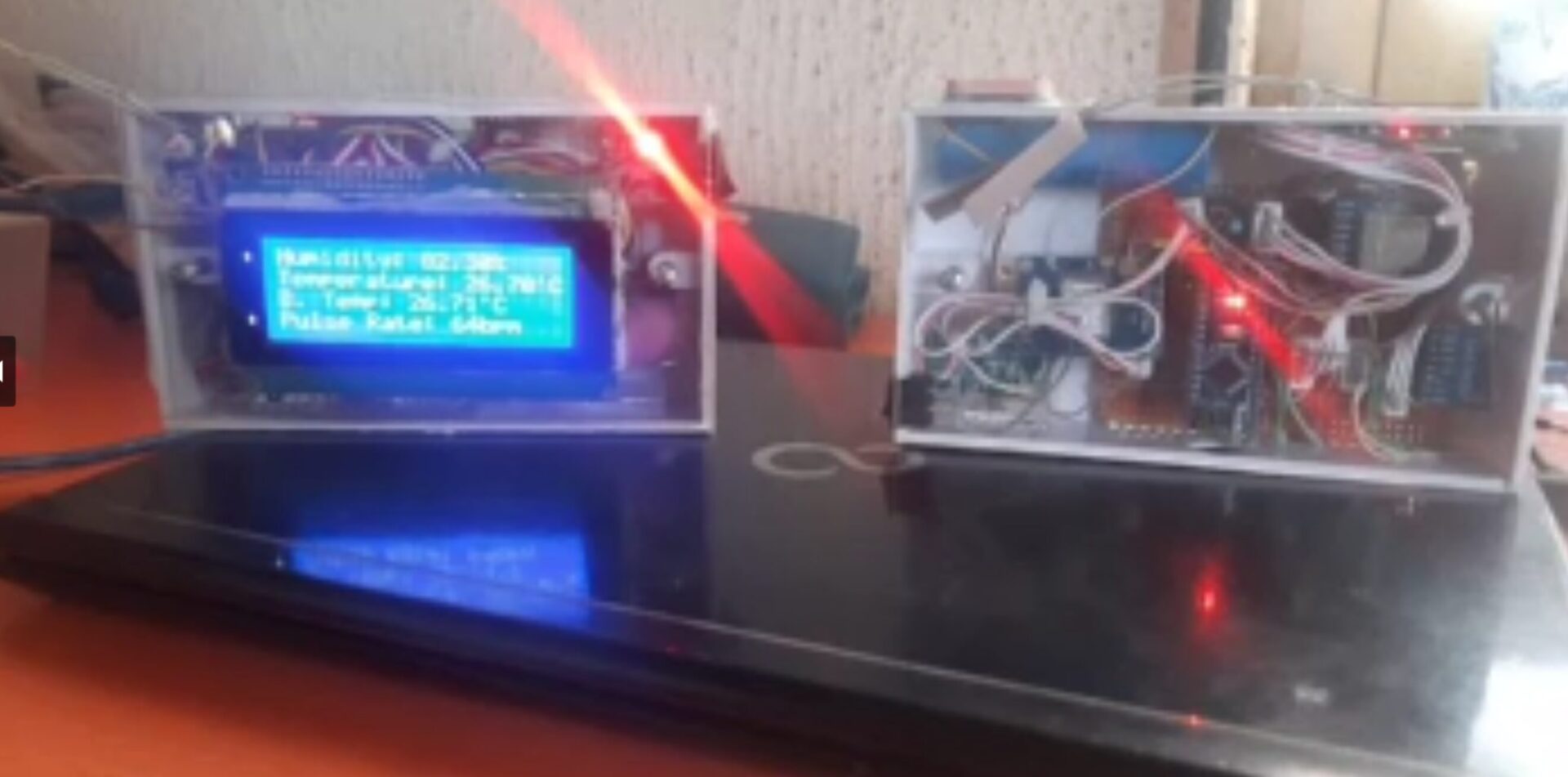
We powered on the transmitter and receiver modules and ensured that data is being sent and received correctly. We also simulated abnormal conditions (e.g., by changing the temperature or pulse rate) to test if the system sends alerts as expected. And it did.
Applications of Smart Livestock Tracking
This system has numerous applications in livestock management:
- Preventing Livestock Theft: By providing real-time GPS data, the system can help farmers quickly locate and recover stolen animals.
- Health Monitoring: The DHT11 and pulse rate sensors ensure that the animal’s health is monitored continuously. Early detection of stress or illness can save the lives of valuable livestock.
- Remote Monitoring: The LoRa and GSM modules enable remote monitoring, meaning farmers don’t need to be physically present to ensure the well-being of their animals.
Advantages of Using IoT in Livestock Management
1. Cost-Effective
Using IoT-based systems like this one is cost-effective in the long run. It reduces the need for manual labor and helps prevent the loss of livestock due to theft or illness.
2. Real-Time Data
Farmers get real-time data on their animals’ location and health, allowing them to make informed decisions quickly.
3. Scalability
This system is scalable, meaning multiple livestock can be tracked simultaneously by adding more transmitters.
Challenges and Future Improvements
While the current system is highly functional, there are a few challenges to address:
- Battery Life: The LiPo battery powering the transmitter needs to be recharged periodically. Using a solar panel to recharge the battery could enhance the system’s autonomy.
- Data Accuracy: While the GPS module provides accurate location data, its performance can be affected by environmental factors such as dense foliage or extreme weather. Using more advanced GPS modules could improve reliability.
- Range of LoRa: The LoRa module’s range is sufficient for most farms, but larger operations may require multiple receivers to cover more ground.
Conclusion
The Smart Livestock Tracker using Arduino, LoRa, and GPS is a powerful tool for modern livestock management. With real-time tracking and health monitoring capabilities, it allows farmers to protect their animals, ensure their well-being, and operate more efficiently. As IoT continues to evolve, systems like this one will become even more integral to the future of farming, offering scalable, cost-effective solutions for livestock management.
Leave us a comment below if you have any questions regarding this project design. And if you replicated it or even upgraded the features than it already is. Let us know too.
FAQs
How far can the LoRa module communicate?
LoRa modules can communicate over distances up to 10 km, depending on the terrain and environmental conditions.
Can this system be adapted for larger herds?
Yes, the system can be scaled by adding more transmitters, allowing multiple animals to be tracked simultaneously.
How does the GSM module send location data?
The GSM module sends an SMS to the farmer with the livestock’s GPS coordinates in the form of a Google Maps link.
Is the system waterproof?
The system components can be housed in waterproof enclosures to protect them from rain or other environmental factors.
What happens if the battery runs out?
If the LiPo battery runs out, the system will stop functioning. Incorporating a solar charging system can help maintain continuous power.


Thats its a good system for tracking livestock.
What can i do to have a workshop (Training) to program the system.
Your respond will be more appriciated
Hi Malatji,
We can give your a consultancy session.
We have sent you full guidelines on how to get on board via your mailbox. Kindly check and give us a reply.
Thank you.
Hi,
Can I get a workshop for developing the animal tracking gadget?
Yes,
Email us: info@smartechmolabs.com.
And sign up for a consultancy session.
That is a very good project. I want to work on the same thing so can i please have assistance
Hi there?
I think you also sent us an email and messaged on IG. We will assign you somebody from our tech team that would give you all the support that you need.
However, this means that you have to sign up for a consultancy session. And this is not FREE.