This project, Smart Automated Flushing System intends to create and install smart toilets specifically made for children in order to address the urgent problem of disease spread in flood-affected communities and Internally Displaced Persons (IDP) camps. These restrooms will have cutting-edge design elements and technology to encourage young ones to practice good hygiene habits and sanitation, reducing the spread of diseases.
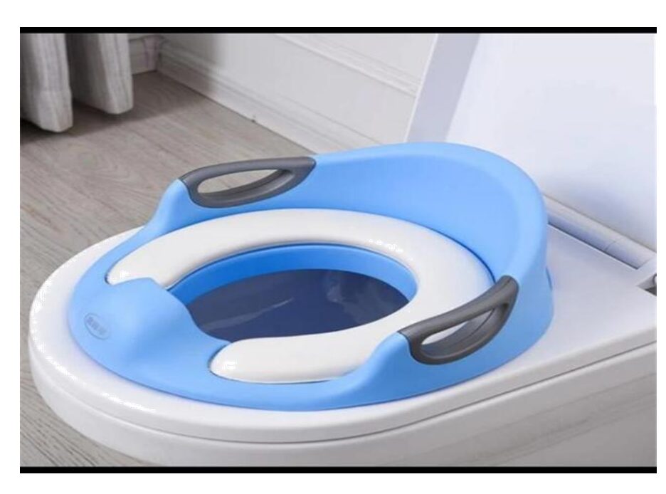
The project’s development of kid-friendly smart toilets that take into account the special requirements and vulnerabilities of kids in flood-affected areas is one of its main goals. These restrooms will have sensors to detect use, automatic flushing and cleaning systems, and feedback systems to teach kids the right techniques for using the restroom and washing their hands. The concept seeks to promote good hygiene, convenient and entertaining sanitation services by:
- Testing and evaluating the effectiveness of the system in improving sanitation and reducing the spread of waterborne diseases in IDP camps
- Designing and developing a smart automated flushing system that is specifically
tailored to the needs and constraints of children. - Promoting adequate water supply and fostering a favorable environment through the effective management of system usage.
The Smart Automated Flushing System For Children Project Methodology
The development of the automatic flushing toilet project followed a specific methodology. Initially, a sketch of the system design was created on paper, followed by a cost analysis to determine the appropriate materials and components. The goal was to select high-quality materials at reasonable prices.

The project aimed to design and construct a contactless automatic flushing toilet, considering children’s use. The toilet system was designed to indicate its state at the door using two indicator lights (a green and red LED). A user could activate the flushing mechanism by swiping their hand over a sensor on the toilet bowl cover, without the need for physical contact. The indicator lights on the door allowed cleaners and service personnel to easily identify if a toilet was operational. The methodology involved the following steps:
- Sketch and Design: A design sketch for the toilet system was made, showing the
frame and general appearance of the setup. - Cost Analysis: To establish the cost-effectiveness of the necessary supplies, a cost analysis was done.
- Construction: The frame of the toilet enclosure was measured and marked before building began. The frame was constructed out of thick wooden rods, and a hole was bored for the waste pipe at the base of the wall. The door and sidewalls were constructed separately from the frame out of plywood and plexiglass. The application of vinyl wraps produced a better finish.
- Installation: The toilet tank was equipped with the sensor-driven flushing kit, ball check valve, and float switch. Additionally, the toilet bowl and a portable toilet were installed.
- Read Face and Fingerprint Recognition Biometric Surveillance Project
- Read DIY Non-Invasive Blood Pressure and Cholesterol Level Monitoring
- Read How to Build DIY Gas Leak Detector with Arduino and Blynk IoT
- Remote Health Monitoring System with ESP32, LoRa, & ThingSpeak
Materials and Components Needed For the Project Design
| ITEM | QUANTITY | UNIT COST | TOTAL UNIT |
| DESCRIPTION | |||
| 3×2 AA BATTERY | 1 | 2,000 | 2,000 |
| BOX | |||
| Connector | 3 | 1500 | 4,500 |
| RESISTORS | 2 | 10 | 20 |
| CONNECTING | 3 yards | 800 | 2,700 |
| WIRES | |||
| VERO BOARD | 1 | 1000 | 1000 |
| AA BATTERY | 2 | 1200 | 1200 |
| RELAY | 2 | 800 | 1,600 |
| TIP41C | 2 | 650 | 1,300 |
| TRANSISTOR | |||
| SOLDER | 1 | 3000 | 6000 |
| SOLDERING | 1 | 2000 | 2000 |
| IRON | |||
| AUTO FLUSHER | 1 | 45,000 | 45,000 |
| UNIT | |||
The table above contains the bill of materials for the project design. Each component or module comes with the exact quantity and the cost in Naira. You can buy most of this at the Smartech shop.
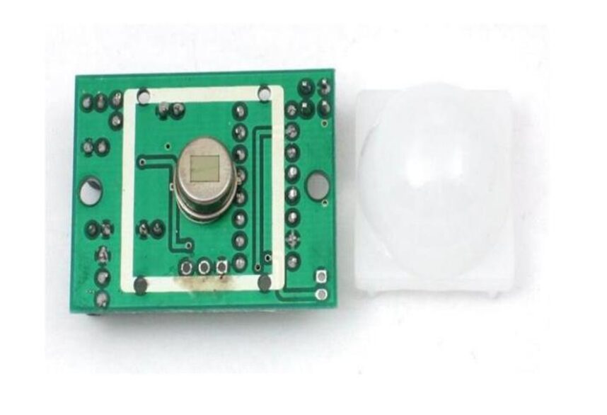
They are sometimes referred to as PIR, or “Pyroelectric infrared motion” detectors. PIR sensors are primarily made of a pyroelectric sensor (which is displayed in the image above: that is the round metal can at the center of the PIR board with a rectangular crystal on top). It detects whether a person has moved out of its range or into its detecting range.
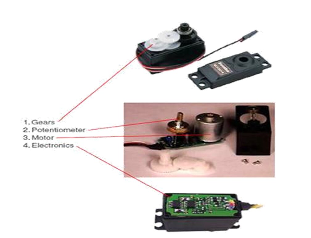
The Servo motor, also referred to as “servo” is an actuator or a rotary device that makes precise angular positioning, acceleration, and velocity possible. Servo motors are manufactured in various sizes with varying torque capabilities. In terms of their mode of operation they can be divided into three types: continuous rotation servos, positional rotation servos, and linear servos. However, servomotors are powered using PWM, regardless of the servo motor type.
The Schematic Diagram for Smart Automated Flushing System Design
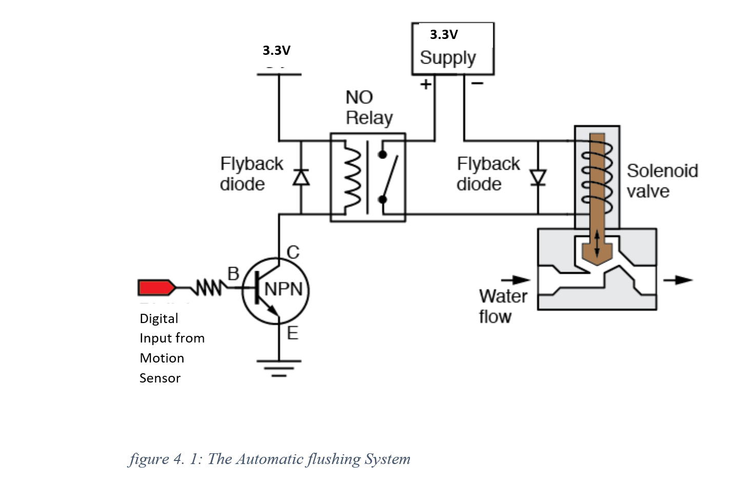
The gesture sensor produces an output signal voltage when it detects user presence or movements. The base of the NPN transistor receives this voltage via a current-controlling 220 resistors. The transistor is activated when the output voltage is high enough, allowing current to flow from the transistor’s collector to its emitter. By coupling its collector to the control pin (coil) of the relay, this active transistor in turn powers it up. As a result, the relay’s typically open contacts close and a circuit is created for the solenoid valve. The solenoid valve opens when the relay is turned on, allowing water to flush the toilet by flowing into the bowl.
When the user exits the system or when flushing is finished, the solenoid valve opens and stays open until the relay is de-energized. After being de-energized, the relay switches back to its normally open position, cutting off power to the solenoid valve and stopping the flow of water.
This circuit offers an automatic flushing system by using the gesture or motion sensor to activate the NPN transistor and manage the NO relay. It makes sure that the solenoid valve only opens when a user is present, conserving water and promoting convenience and hygiene when flushing the toilet. The system’s overall efficiency is also improved by the incorporation of a low-power solenoid valve and a battery power source.
The gesture made at the IR based motion sensor at the metal faceplate base the transistor which will energize the relay. And the solenoid valve will be energized and the plunger would be pulled up. Allowing water to flow. Since the flusher water tank was kept at a high, the pressure equation given below prevails and the water will flow flushing the toilet.
p = g ×ℎ×⍴
Where g = acceleration due to gravity, h = height of the flusher tank and ⍴ = the density of the fluid.
The schematic diagram used a fly back diode to ensure electromagnetic energy is burned out when the relay is turned off or when the solenoid valve is de-energized. An output is reserved for the indication of when the toilet is available to use or not.
Explanation of the Schematic Diagram
Interfacing the Automatic Flusher Unit
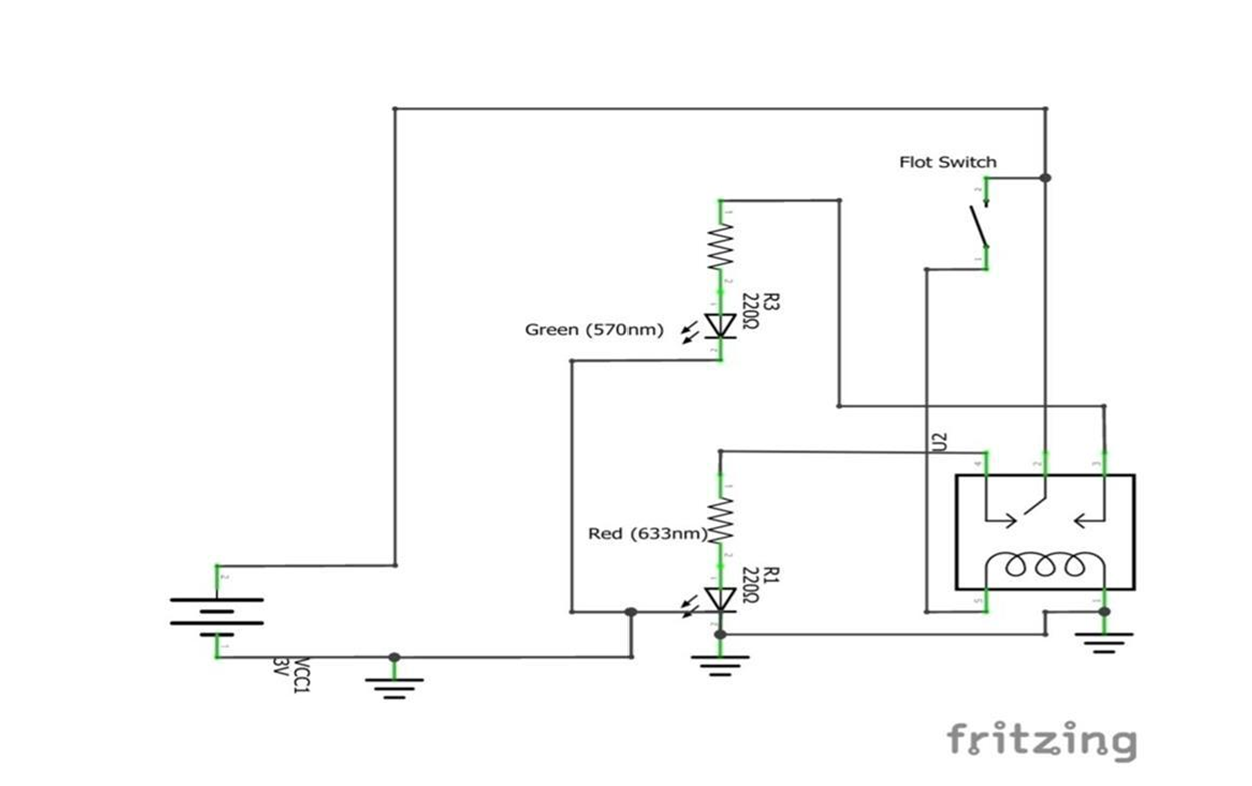
The schematic diagram provided shows how an automatic flushing device works by triggering the flushing process using a gesture or motion sensor. Here is an in-depth breakdown of each part and its function:
Gesture/Motion sensor:
- The gesture or motion sensor is used to detect user presence or movement near the toilet area.
- It produces an output signal voltage that changes in accordance with the motions or gestures that are detected.
NPN transistors:
- The NPN transistor play a role as a switch in this circuit
- The base of the NPN transistor is activated when the output signal voltage from the gesture sensor is present.
220Ω Resistor:
- The 220Ω resistor is connected between the output of the gesture sensor and the base of the NPN transistor.
- It serves as a current limiter, limiting the amount of current that can pass through the transistor.
NO Relay (Normally Open Relay):
- The NO relay is used to control the solenoid valve of the auto flusher.
- It has two states which are normally open (NO) and normally closed (NC).
- When the relay is not energized, the NO contacts remain open.
Low Power Solenoid Valve:
- The solenoid valve is used to control the water flow and initiate flushing process.
- It is connected to the power supply line of the toilet
- It consumes low power
- It can operate with voltages as low as 3.3V which is suitable for use with double AA battery as the source of power.
Read Also…
- Medical Consequences of Organ Donation Policies!
- Should Teens Be Allowed to Obtain Birth Control Pills?
- How Poverty Devastates Health
- Turning Your Creative Side Hustle into a Profitable Venture
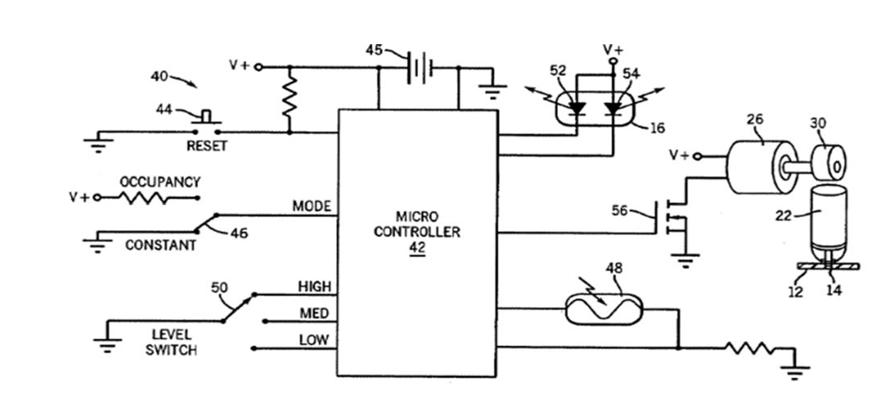
Interfacing the Automatic Air Freshener Unit
Assembling The Project Design Together

The construction began with measuring and marking out the dimensions of the toilet enclosure, starting with the frame as shown below. A height of 3ft6″ with a length of 3ft6″ and a breadth of 3ft as shown in the design sketch above were the design measurements for the frame. Very thick wooden rods measuring 2.75″ in thickness were used to ensure a study frame was achieved.
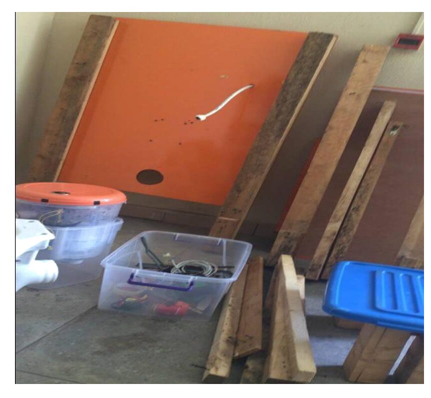
Thence a base dimension of 3ft6″ by 3ft was constructed. The plywood chosen was a ¾ inch thick MDF. The wooden rods for the frames were cut to the right height using a band saw, and the edges were smoothened with a table saw to remove splinters of wood and avoid potential injuries. A large hole about 4½ inch diameter was cut using a drill machine at the base of the wall which would sit the toilet tank. This hole would allow for the waste pipe from the toilet bowl to pass through and deliver waste water into the waste/septic tank
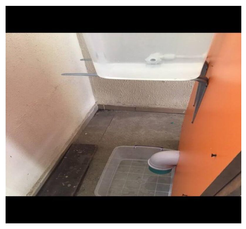
After these were done, the sidewalls and the door were fabricated separately from a ¼ inch thick plywood and plexiglass, measuring 3ft X 3ft6″ in breadth and length. Once they were prepared, they were attached to the toilet enclosure frame as shown in the images below. The LED bulb indicator circuit was also attached to the door, with both LED bulbs fixed at the entrance to the door, so a user notices them first before entering and using the toilet.
Test Results and Analysis
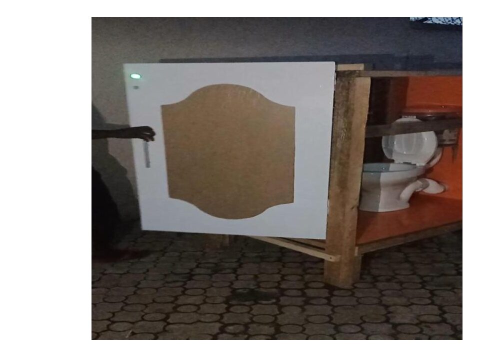
The construction of the toilet system was completed and tested. The test yielded positive and expected results; which were a contactless flushing system and an indicator system for the state of the toilet.
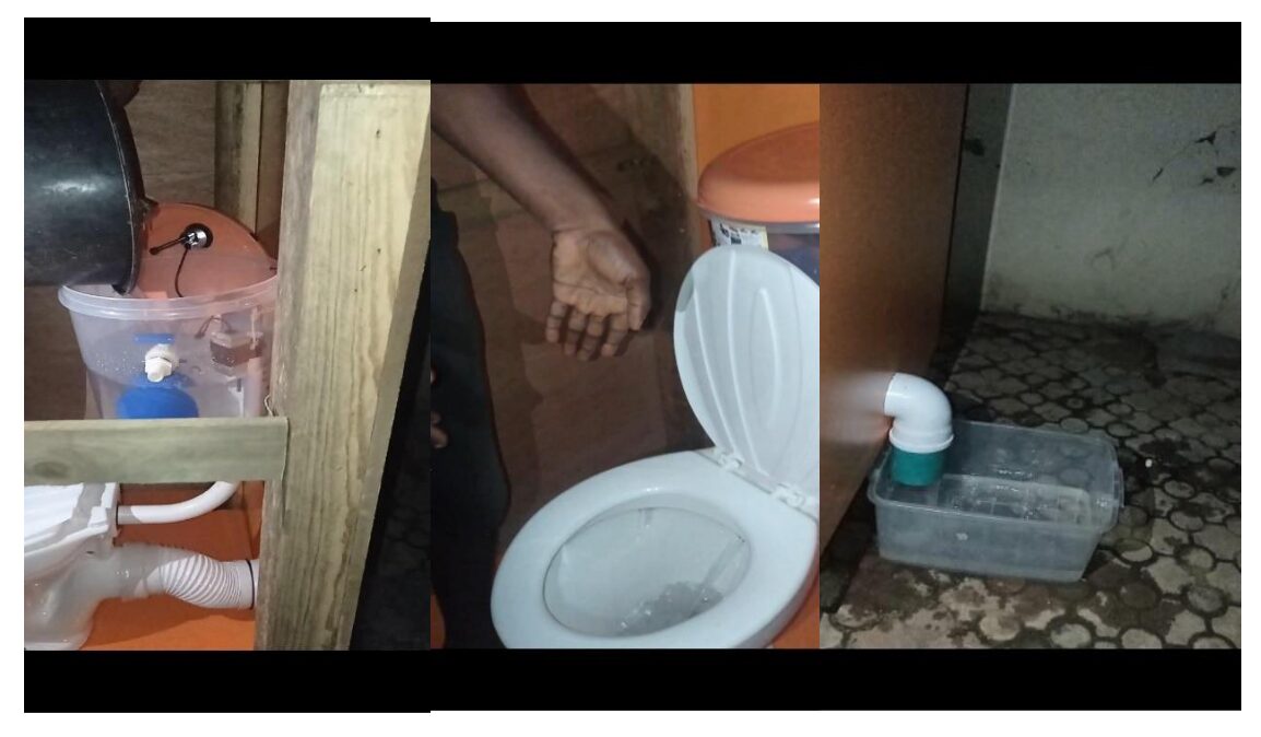
Image showing the filling of the toilet tank with water to be used for flushing, the toilet flushing after the swipe of a user’s hand, and the waste water leaving the bowl into the assumed septic tank. When a gesture is made over the Infrared (IR) motion sensor, the toilet flushes as shown in the image above. For this to happen however, the water level sensor ensures that there is enough water in the flusher reservoir to be able to flush the toilet. This is indicated by the green LED as shown below.
Conclusion
The smart automated flushing system design has been implemented and it performed very well within the scope of its design. We would like to know if you followed our footsteps here and replicated the same project or if you upgraded yours too. Please leave us a comment below.
Frequently Asked Questions
1. What is a Smart Automated Flushing System?
A Smart Automated Flushing System is a modern upgrade to traditional toilet systems that automates the flushing process. It typically uses sensors to detect when the toilet has been used and automatically flushes it without requiring manual intervention. This technology helps maintain hygiene, conserve water, and reduce the spread of germs.
2. How does a Smart Automated Flushing System work?
The system uses sensors, such as infrared or ultrasonic sensors, to detect user presence or motion. When the user steps away or makes a specific gesture, the system activates the flushing mechanism, usually via a motor or servo connected to the toilet’s flush handle or valve. Some systems also monitor the water level in the tank to ensure sufficient water is available for flushing.
3. What are the benefits of using a Smart Automated Flushing System?
The key benefits include improved hygiene by eliminating the need for physical contact, reduced water usage through controlled and efficient flushing, and increased convenience. In public restrooms, these systems help maintain cleanliness and reduce maintenance needs. Additionally, they can be programmed to flush at specific intervals, preventing waste buildup in low-traffic areas.
4. Can I install a Smart Automated Flushing System in my existing toilet?
Yes, most Smart Automated Flushing Systems are designed to be retrofitted onto existing toilets. Installation usually involves mounting the sensor and actuator near the flush handle or valve and connecting it to a power source. Some systems are battery-powered, while others may require a connection to your home’s electrical system.
5. What happens if the sensor fails or the system malfunctions?
In case of sensor failure or system malfunction, most Smart Automated Flushing Systems allow for manual flushing as a backup. It’s important to choose a system with reliable components and consider models that include a manual override feature. Regular maintenance, such as checking the sensor alignment and battery life, can also prevent malfunctions.
6. Is the Smart Automated Flushing System suitable for public restrooms?
Yes, the Smart Automated Flushing System is particularly well-suited for public restrooms where high traffic and hygiene are priorities. These systems minimize the risk of germ transmission by reducing touchpoints and help keep restrooms cleaner by ensuring that toilets are flushed after each use. They also support water conservation efforts by using precise amounts of water per flush.

