Imagine a world where your doorbell is not just a mundane button but an intelligent device that notifies you, streams live video, and even emails you a snapshot of your visitor. Intriguing, right? Thanks to IoT (Internet of Things), Arduino, and platforms like Blynk, you can create an IoT smart doorbell system that transforms how you interact with your front door.

In this comprehensive guide, we’ll explore how to build an IoT Smart Doorbell with an ESP32-CAM, an ESP8266-12E module for internet connectivity, a pushbutton, a PIR motion sensor, and the Blynk IoT platform for seamless interaction.
Why Build an IoT Smart Doorbell?
Conventional doorbells are outdated in today’s connected world. A smart doorbell offers:
- Real-Time Notifications: Alerts you whenever someone is at the door.
- Remote Monitoring: Lets you see and interact with visitors even if you’re not at home.
- Enhanced Security: Captures images and streams video to ensure you never miss unexpected visitors.
If you’re a tech enthusiast, this project is an exciting way to combine creativity and functionality.
Read Also: How to Know the Best Cryptocurrency Exchanges for your Investment
Key Components for the Smart Doorbell

To build this project, you’ll need:
- ESP32-CAM: For capturing images and streaming live video.
- ESP8266-12E: For internet connectivity and communication with Blynk.
- PIR Motion Sensor (HCSR505): To detect motion near the door.
- Pushbutton: To trigger email alerts and video streaming.
- Blynk IoT Platform: For managing notifications, video streaming, and data visualization.
- Power Supply: A 5V adapter or battery pack for the ESP32-CAM and ESP8266.
- Breadboard and Wires: For prototyping and connections.
- 1k resistor
How the System Works

- Motion Detection with PIR Sensor: The PIR sensor detects movement near the door, waking up the ESP32-CAM from low-power mode.
- Pushbutton Interaction: When the button is pressed, the ESP32-CAM captures an image and sends an email alert to your mailbox.
- Live Video Streaming: The ESP32-CAM streams live video to your Blynk app’s video widget.
- Remote Notifications: The ESP8266-12E ensures real-time updates through the internet, enabling you to stay informed wherever you are.
Step-by-Step Guide to Building the IoT Smart Doorbell
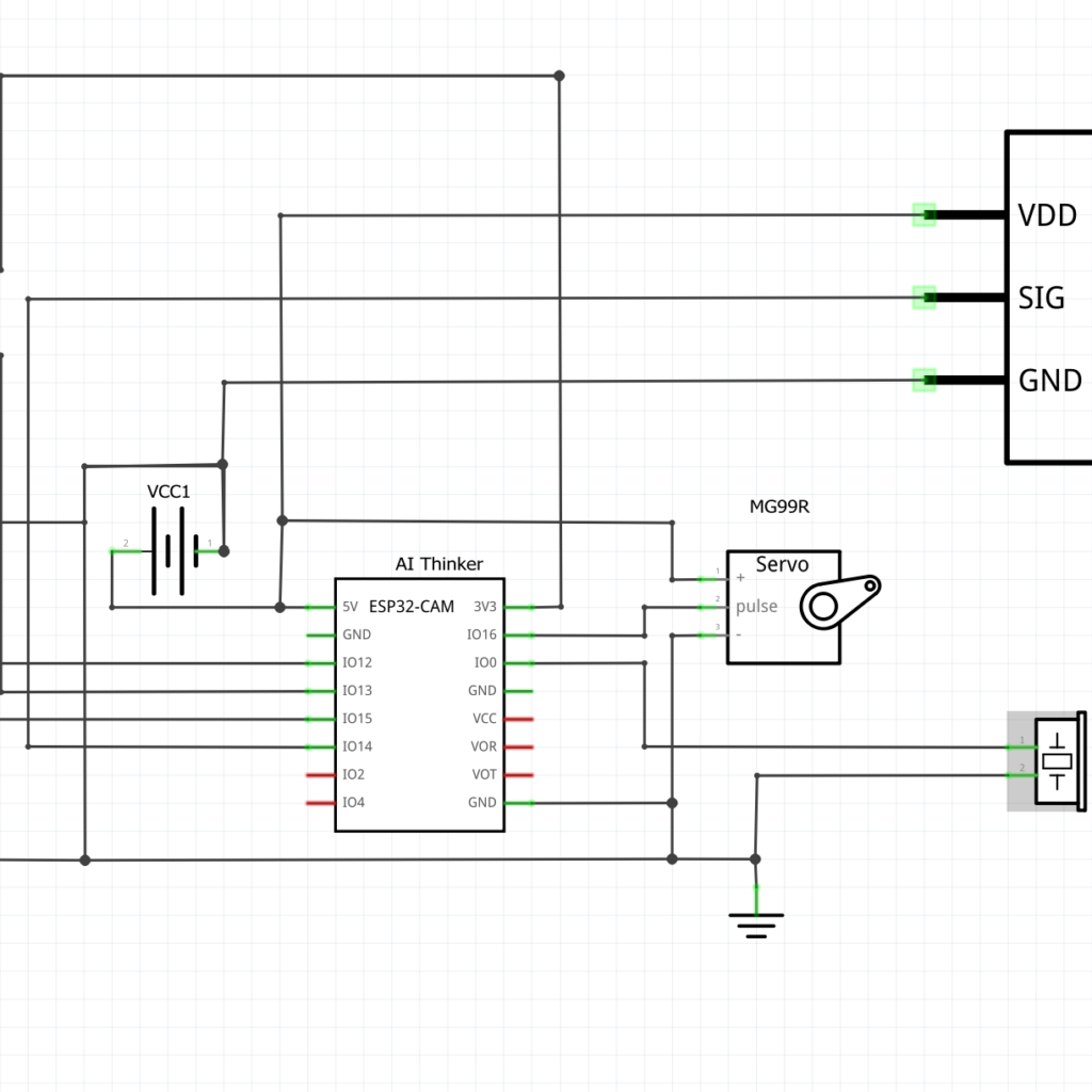
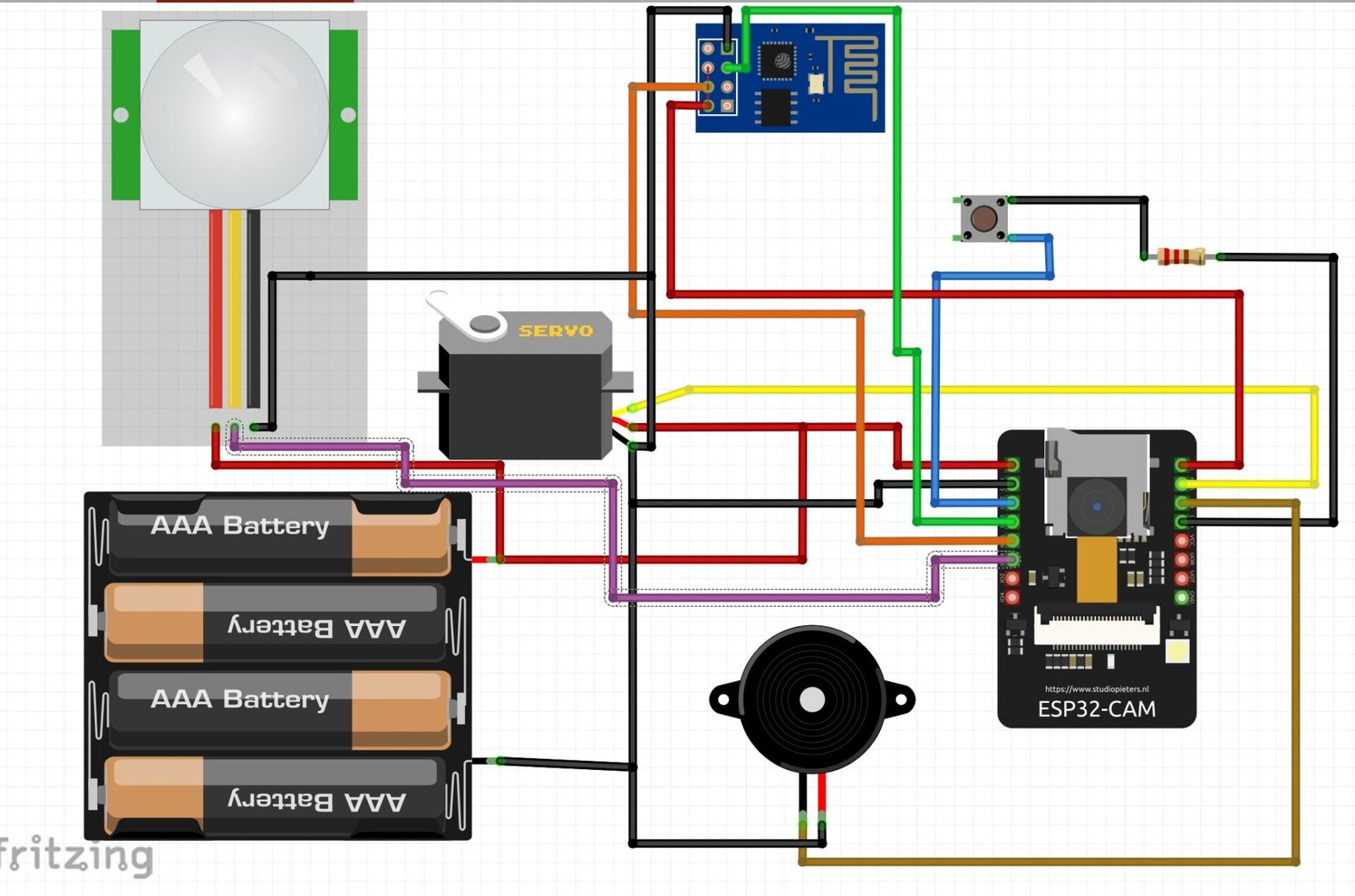
The Schematic Diagram for Setting Up the Hardware

Explanation of Circuit Diagram and ESP32-CAM Connections
We added a buzzer to let the visitor know when he/she is pressing the pushbutton alert for the smart doorbell. Also the battery displayed here can be made to be rechargeable. We added a servo motor to change the direction of the camera. The PIR motion sensor can also be used to put the camera in video streaming mode.
- Connect the ESP32-CAM to your power supply.
- Link the pushbutton to a GPIO pin on the ESP32-CAM.
- Integrate the PIR sensor to another GPIO pin for motion detection.
Reas Also: Injury Prevention: Common Workout Mistakes and How to Avoid Them
ESP8266-12E Integration
The schematic diagram shows the ESP8266 was connected using software serial method to send the data to the Blynk IoT platform.
- Use the ESP8266 to connect the ESP32-CAM to Wi-Fi.
- Configure it for communication with the Blynk platform.
Installing Necessary Libraries
Download and install the following libraries in the Arduino IDE:
- ESP32 Library: For programming the ESP32-CAM.
- Blynk Library: For integrating with the Blynk platform.
- Email Client Library: For sending email alerts.
Coding the Smart Doorbell (The Arduino Programming)
#include <WiFi.h>
#include <ESP32_MailClient.h>
#include <BlynkSimpleEsp32.h>

// Replace with your network credentials
const char* ssid = "YOUR_WIFI_SSID";
const char* password = "YOUR_WIFI_PASSWORD";

// Email configuration
#define SMTP_HOST "smtp.gmail.com"
#define SMTP_PORT 465
#define AUTHOR_EMAIL "YOUR_EMAIL@gmail.com"
#define AUTHOR_PASSWORD "YOUR_EMAIL_PASSWORD"
#define RECIPIENT_EMAIL "RECIPIENT_EMAIL@gmail.com"

// PIR and pushbutton pins
#define PIR_PIN 13
#define BUTTON_PIN 12

// Camera initialization
#include "esp_camera.h"
#define PWDN_GPIO_NUM     -1
#define RESET_GPIO_NUM    -1
#define XCLK_GPIO_NUM      0
#define SIOD_GPIO_NUM     26
#define SIOC_GPIO_NUM     27
#define Y9_GPIO_NUM       35
#define Y8_GPIO_NUM       34
#define Y7_GPIO_NUM       39
#define Y6_GPIO_NUM       36
#define Y5_GPIO_NUM       21
#define Y4_GPIO_NUM       19
#define Y3_GPIO_NUM       18
#define Y2_GPIO_NUM        5
#define VSYNC_GPIO_NUM    25
#define HREF_GPIO_NUM     23
#define PCLK_GPIO_NUM     22

// Blynk credentials
char auth[] = "YOUR_BLYNK_AUTH_TOKEN";

// SMTP client
SMTPData smtp;

// Function to send email
void sendEmailWithImage() {
  camera_fb_t * fb = NULL;

  fb = esp_camera_fb_get();
  if (!fb) {
    Serial.println("Camera capture failed");
    return;
  }

  smtp.setLogin(SMTP_HOST, SMTP_PORT, AUTHOR_EMAIL, AUTHOR_PASSWORD);
  smtp.setSender("Smart Doorbell", AUTHOR_EMAIL);
  smtp.setPriority("High");
  smtp.setSubject("Visitor at Your Door!");
  smtp.setMessage("Motion detected or button pressed. Attached is the image of the visitor.", false);

  smtp.addAttachment("visitor.jpg", fb->buf, fb->len);
  smtp.addRecipient(RECIPIENT_EMAIL);

  if (!MailClient.sendMail(smtp)) {
    Serial.println("Error sending Email, " + MailClient.smtpErrorReason());
  } else {
    Serial.println("Email sent successfully!");
  }

  smtp.empty();
  esp_camera_fb_return(fb);
}

void setup() {
  // Serial monitor
  Serial.begin(115200);

  // Initialize WiFi
  WiFi.begin(ssid, password);
  while (WiFi.status() != WL_CONNECTED) {
    delay(500);
    Serial.print(".");
  }
  Serial.println("\nWiFi connected!");

  // Initialize Blynk
  Blynk.begin(auth, ssid, password);

  // Initialize Camera
  camera_config_t config;
  config.ledc_channel = LEDC_CHANNEL_0;
  config.ledc_timer = LEDC_TIMER_0;
  config.pin_d0 = Y2_GPIO_NUM;
  config.pin_d1 = Y3_GPIO_NUM;
  config.pin_d2 = Y4_GPIO_NUM;
  config.pin_d3 = Y5_GPIO_NUM;
  config.pin_d4 = Y6_GPIO_NUM;
  config.pin_d5 = Y7_GPIO_NUM;
  config.pin_d6 = Y8_GPIO_NUM;
  config.pin_d7 = Y9_GPIO_NUM;
  config.pin_xclk = XCLK_GPIO_NUM;
  config.pin_pclk = PCLK_GPIO_NUM;
  config.pin_vsync = VSYNC_GPIO_NUM;
  config.pin_href = HREF_GPIO_NUM;
  config.pin_sccb_sda = SIOD_GPIO_NUM;
  config.pin_sccb_scl = SIOC_GPIO_NUM;
  config.pin_pwdn = PWDN_GPIO_NUM;
  config.pin_reset = RESET_GPIO_NUM;
  config.xclk_freq_hz = 20000000;
  config.pixel_format = PIXFORMAT_JPEG;

  if (psramFound()) {
    config.frame_size = FRAMESIZE_UXGA;
    config.jpeg_quality = 10;
    config.fb_count = 2;
  } else {
    config.frame_size = FRAMESIZE_SVGA;
    config.jpeg_quality = 12;
    config.fb_count = 1;
  }

  // Camera init
  esp_err_t err = esp_camera_init(&config);
  if (err != ESP_OK) {
    Serial.printf("Camera init failed with error 0x%x", err);
    return;
  }

  // Pin modes
  pinMode(PIR_PIN, INPUT);
  pinMode(BUTTON_PIN, INPUT_PULLUP);
}

void loop() {
  Blynk.run();

  // Check for PIR motion detection
  if (digitalRead(PIR_PIN) == HIGH) {
    Serial.println("Motion detected!");
    sendEmailWithImage();
    delay(10000); // Debounce delay to prevent multiple triggers
  }

  // Check for button press
  if (digitalRead(BUTTON_PIN) == LOW) {
    Serial.println("Button pressed!");
    sendEmailWithImage();
    delay(10000); // Debounce delay
  }
}
The code for this project is divided into multiple sections:
- Wi-Fi Connection: Configure the ESP8266 to connect to your Wi-Fi network.
- Motion Detection: Program the ESP32-CAM to respond to the PIR sensor.
- Image Capture and Email: Write a function to take a snapshot and send it via email.
- Blynk Video Stream: Set up the video widget in the Blynk app for live streaming.
Configuring the Blynk IoT Platform
- Create a New Project: Open the Blynk app and create a new project.
- Add Widgets: Include the video stream widget for live feed and notification widgets for alerts.
- Get the Auth Token: Copy the token for use in your Arduino code.
Optimizing the PIR Motion Sensor
Why Use the HCSR505 PIR Sensor?

The HCSR505 is a compact, low-power motion sensor that works perfectly for detecting human movement.
Filtering Motion from Pets
To minimize false triggers from pets:
- Adjust the sensitivity pot on the sensor.
- Limit the sensor’s detection range using a focused lens or physical barriers.
Read Also: How to Prepare Recipes for Regulating Blood Sugar
Advantages of Using Blynk
Blynk is a user-friendly IoT platform that simplifies the process of connecting devices to the cloud.
- Real-Time Control: Manage your doorbell system from anywhere.
- Video Streaming: Watch visitors in real-time.
- Easy Customization: Add widgets for additional features, such as logging visitor data.
Challenges and Solutions
1. False Triggers from PIR Sensor
- Solution: Adjust the sensor’s sensitivity or use AI for motion filtering.
2. Network Connectivity Issues
- Solution: Use a reliable Wi-Fi network and implement reconnection logic in your code.
3. Power Consumption
- Solution: Utilize the ESP32-CAM’s deep sleep mode and wake it only when motion is detected.
Enhancing the System
1. Two-Way Audio
Add a microphone and speaker to enable communication with visitors.
2. Night Vision
Use IR LEDs with the ESP32-CAM for clear night-time images.
3. Cloud Storage
Store captured images and videos on a cloud service like Google Drive for future reference.
4. AI-Powered Detection
Integrate AI to distinguish between humans, pets, and inanimate objects.
Applications of the IoT Smart Doorbell
- Home Security: Monitor your front door in real-time.
- Office Entry Systems: Enhance access control and visitor logging.
- Elderly Assistance: Notify caregivers when someone is at the door.
Conclusion
Building an IoT Smart Doorbell with Arduino, ESP32-CAM, and Blynk combines creativity, functionality, and security. This project not only upgrades your home’s entry system but also introduces you to exciting IoT concepts. Whether you’re a tech enthusiast or someone looking to enhance their home security, this project is a perfect blend of innovation and practicality.
So, are you ready to build your smart doorbell and take your DIY skills to the next level?
FAQs
1. Can I use a different motion sensor instead of the HCSR505?
Yes, you can use advanced motion sensors like the Omron D6T for more precise detection.
2. What is the range of the HCSR505 PIR motion sensor?
The HCSR505 has a range of about 3-7 meters and a detection angle of 100 degrees.
3. How do I ensure the email alert works reliably?
Use a stable internet connection and configure your email server settings properly in the code.
4. Can this system work without the Blynk platform?
Yes, you can use alternatives like MQTT or Firebase for notifications and data handling.
5. Is it possible to store visitor images locally?
Yes, you can store images on an SD card connected to the ESP32-CAM for local storage.

