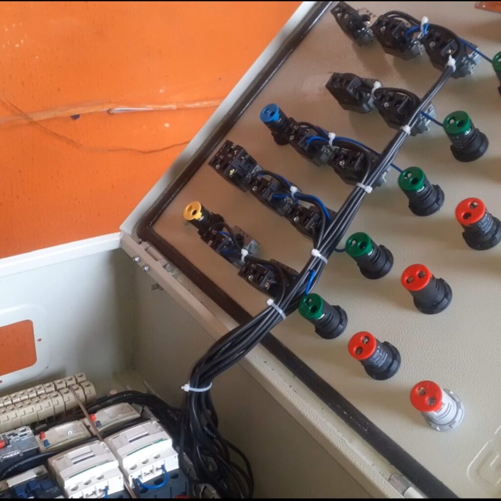
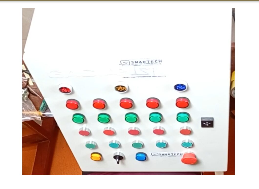
In today’s how-to tutorial, we will be going through how to design a direct online starter control panel for five (5) 3-phase motors. This control panel can control 3-phase motors up to 5 motor capacity.
The industrial world hums with the tireless work of electric motors. To safely and efficiently control these workhorses, direct online (DOL) starters play a crucial role. This blog delves into the design process of a DOL starter for 3-phase motors, equipping you with the knowledge to bring your project to life.
Introduction
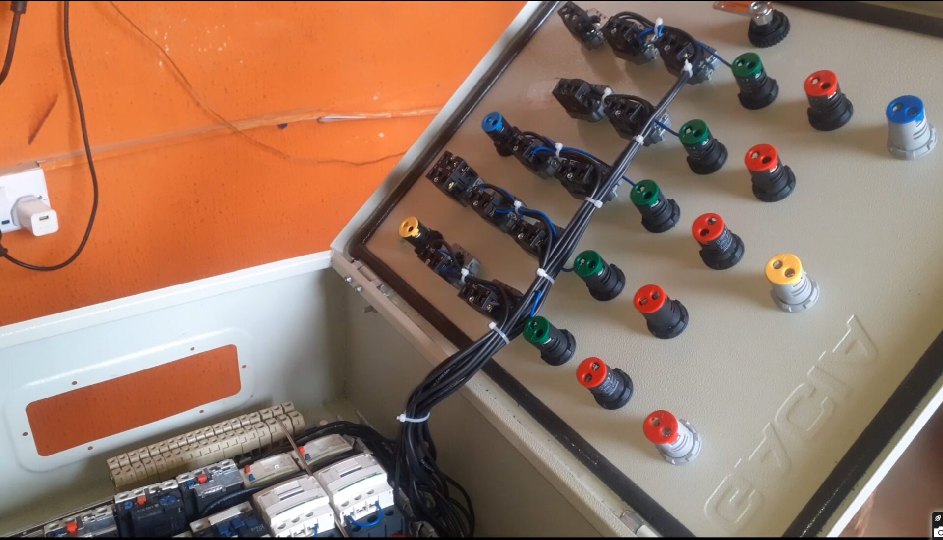
Imagine a factory floor devoid of the rhythmic whirring of motors. DOL starters bridge the gap between the power grid and these essential machines, ensuring smooth operation and protecting them from harm. Let’s embark on a journey to understand the design process of a DOL starter for 3-phase motors, making you a whiz at crafting this fundamental industrial control device.
Before we dive into design, let’s meet the key components that make a DOL starter tick:
- Magnetic Contactor: This heavy-duty switch acts as the heart of the starter. When energized, its electromagnet pulls in a metal contactor arm, completing the circuit and supplying power to the motor.
- Overload Protection: Essential for safety, overload protection devices like thermal relays monitor motor current. If excessive current flows, the relay trips, cutting power and preventing motor damage.
- Control Circuit: This low-voltage circuit governs the contactor. Push buttons, control switches, and pilot lights are often part of this circuit.
- Power Circuit: This high-voltage circuit carries the actual power from the supply to the motor, passing through the contactor.
The Design Flowchart: A Step-by-Step Guide
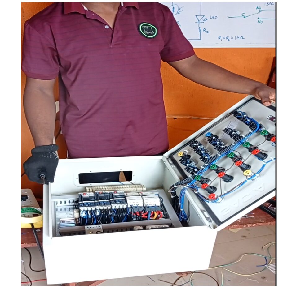
Now, let’s break down the design process into a series of manageable steps:
- Motor Selection and Sizing: The first step is to determine the specific 3-phase motor you’ll be controlling. Factors like motor horsepower (HP), voltage rating, and full-load current (FLA) are crucial for selecting appropriate starter components.
- Contactor Selection: Based on your motor’s FLA, choose a contactor with a current rating exceeding the motor’s FLA. Consider factors like voltage compatibility (AC or DC coil) and number of poles (typically 3 for 3-phase motors).
- Overload Protection Selection: Thermal overload relays are commonly used. Select a relay with a current range encompassing your motor’s FLA. Adjustable relays offer flexibility.
- Control Circuit Design: This circuit typically operates at a lower voltage (e.g., 24V DC) for safety. Here’s a breakdown of common elements:
- Start Push Button: Momentary contact switch that energizes the contactor coil when pressed.
- Stop Push Button: Momentary contact switch that breaks the control circuit, de-energizing the contactor and stopping the motor.
- Normally Closed Contact (NC) of the Overload Relay: This contact is in series with the contactor coil and opens (trips) when overload occurs, interrupting power.
- Pilot Light (Optional): Provides visual confirmation of contactor status (on/off).
- Power Circuit Design: This high-voltage circuit carries the brunt of the current. Use appropriately sized conductors based on motor FLA and local electrical codes. Connect the three-phase power supply to the contactor and the motor terminals.
- Enclosure Selection: Choose a sturdy enclosure with a suitable ingress protection (IP) rating to shield the starter from dust, moisture, and accidental contact. Consider factors like accessibility and ventilation.
Putting it All Together: Wiring and Schematics
Please contact us via any of this handles here below for the professional schematic diagram for this work. Due to proprietary reasons, we couldn’t make the schematic diagram open-source. kindly reach out to us here.
Email us:
Telegram:
WhatsApp:
Facebook:
Instagram:
Once you have selected the components, it’s time to translate your design into reality. Here’s where understanding electrical schematics and wiring practices becomes crucial. Here’s a general outline:
- The power circuit connects the three-phase supply to the contactor’s main terminals and then to the motor terminals.
- The control circuit connects the low-voltage power source (e.g., transformer) to the start button, stop button, overload relay NC contact (in series), and contactor coil.
- A pilot light can be connected across the contactor coil to provide visual feedback.
Read Also…
- How to Design and Build an IoT-based Power Backup System
- How To Design A Programmable Electronic Load Controller (ELC) Panel Design
Safety First: Essential Considerations
Safety is paramount when working with electrical circuits.
- Always consult a qualified electrician for complex installations or if you lack the necessary expertise.
- Follow all local electrical codes and safety regulations.
- Double-check your wiring connections before energizing the circuit.
- Use appropriate personal protective equipment (PPE) like insulated gloves and safety glasses when working on electrical equipment.
- Clearly label all components within the enclosure for easy identification.
Testing and Commissioning
With the wiring complete and safety measures in place, it’s time to test your DOL starter. Here’s a simplified approach:
- Isolating Power: Ensure the main power supply is disconnected before any testing procedures.
- Visual Inspection: Double-check all wiring connections for tightness and proper routing.
- Control Circuit Testing: Apply low voltage to the control circuit and verify that the contactor coil energizes when the start button is pressed and de-energizes when the stop button is pressed or the overload relay trips.
- Motor Jogging (Optional): With the main power supply still off, momentarily energize the contactor to ensure the motor rotates freely (jogging). Listen for any abnormal noises or vibrations.
- Powering Up (Final Step): Once satisfied with the control circuit and motor jogging (if performed), reconnect the main power supply and test the overall functionality of the DOL starter. Observe the motor starting and stopping smoothly, and verify overload protection by simulating an overload condition (consult a qualified electrician for safe overload testing procedures).
Advanced Considerations
While the core design principles remain the same, there are additional elements you might encounter in more complex DOL starter applications:
- Motor Protection Circuit Breakers (MPCBs): These combine overload and short-circuit protection within a single device, offering a more compact solution.
- Time Delay Relays: Used to prevent frequent start-stop cycles for motors with high inrush currents, allowing the motor to reach operating speed before re-energizing.
- Electronic Overload Relays: These offer more precise and adjustable overload protection compared to traditional thermal relays.
Tips for Efficiency and Performance
While a basic DOL starter gets the job done, here are some additional considerations to optimize your design for efficiency and performance:
- Motor Starting Characteristics: Understanding the starting current (inrush current) of your motor is crucial. High inrush currents can cause voltage dips and stress electrical components. Consider soft-start devices to mitigate this effect, ensuring smoother motor starts and reducing wear and tear on the starter components.
- Control Circuit Flexibility: Using modular components like terminal blocks and relays allows for easier modifications and future additions to the control circuit. This is especially beneficial if your project requirements might evolve.
- Remote Control Options: For applications requiring remote start/stop functionality, consider incorporating push buttons, control switches, or even wireless control modules into the design.
- Monitoring and Diagnostics: Integrating features like motor running indicators, fault lamps, or even ammeters into the control panel can provide valuable insights into the motor’s operation and aid in troubleshooting any potential issues.
- Also consider checking up on NEMA, they provide industry standards and guidelines for electrical equipment, including motor starters.
Conclusion
By following these steps and considerations, you’ve gained valuable knowledge on designing a direct online starter for 3-phase motors. Remember, safety is paramount, and consulting a qualified electrician is crucial for complex installations. With this newfound expertise, you’re well on your way to controlling the powerhouses that drive the industrial world!
FAQs about Designing Direct Online Starter for 3-Phase Motors
1. What are some additional components I might encounter in complex DOL starter applications?
Your design might include motor protection circuit breakers (MPCBs) for combined overload and short-circuit protection, time delay relays to prevent frequent start-stop cycles, or electronic overload relays for more precise protection.
2. How can I optimize my DOL starter design for efficiency?
Consider using soft-start devices to mitigate high inrush currents during motor startup. This reduces stress on the electrical components and ensures smoother operation. Additionally, using modular components in the control circuit allows for easier future modifications and improves overall flexibility.
3. Can I remotely control a DOL starter?
Absolutely! You can incorporate push buttons, control switches, or even wireless control modules into the design to enable remote start/stop functionality.
4. What are some ways to monitor the performance of a DOL starter?
Integrating features like motor running indicators, fault lamps, or even ammeters into the control panel provides valuable insights into motor operation and helps with troubleshooting potential issues.
5. Where can I find more information about designing DOL starters?
Here are some resources to delve deeper:
- National Electrical Manufacturers Association (NEMA): Provides industry standards and guidelines for electrical equipment, including motor starters.
- Manufacturer Datasheets: Consult the technical specifications and application notes for your chosen starter components.
