The objective of this project is to develop and build an Arduino-based IoT platform temperature control and monitoring system that reads and adjusts the temperature and humidity around the poultry farm living quarters using a digital humidity and temperature sensor, DHT11. A chicken’s body temperature typically ranges from 41.5 degrees Celsius to 42.5 degrees Celsius, depending on its surroundings, as long as air movement—which typically ranges from 10 to 15 degrees below the body temperature—is present. The Arduino unique microcontroller Atmega328P-PU, which was designed to communicate with a Wi-Fi module using the Arduino IDE, would form the foundation of the proposed system.
The Android phone and Wi-Fi module will be linked so that the status of this chicken farm may be viewed and managed remotely from that device. The Android device would run an app that was created exclusively with MIT AI2 AppInventor or RemoteXY to show the temperatures on its screen. The app would also allow the user(s) to control the temperature by pressing a button on the screen, which would eliminate the need for energy-sucking tungsten AC bulbs. Having now had a broad understanding of the project design. A little introduction is provided before we get into the specifics of how to create the temperature monitoring design for chicken farms using the Android platform.
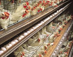
Why Do We Need to Monitor Temperature In Poultry Farms
According to expert advice on chicken farming, a farm’s temperature parameter accounts for two thirds of the environmental influence on its live stocks, in this example, birds. For instance, the ideal temperature range for incubating chicken eggs is between 99 and 102 degrees Fahrenheit. Day-old chicks maintain steady growth at approximately 92 degrees Fahrenheit. A 2009 study found that hot weather has a detrimental impact on domestic animals’ performance and general health. Heat stress brought on by high temperatures increases chicken production’s mortality rate and financial loss. Birds must maintain thermobalance in order to be in harmony with their surroundings and function at their best.
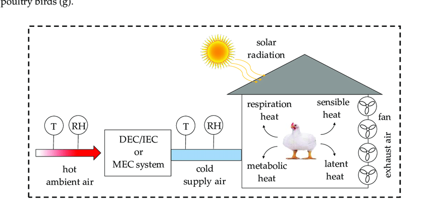
The equilibrium between the quantity of heat released by a living thing at any given time and the amount of heat it produces is known as thermobalance. And within any specific species’ thermoneutral range, this is said to be at its maximal physiological level. As homoeothermic mammals, birds can tolerate some temperature variation without experiencing a severe disruption, yet they nevertheless maintain a generally steady body temperature.
IoT Based Temperature Control Poultry Farm Arduino: Components Needed
| Components | Quantity |
|---|---|
| Arduino Uno board | 1 |
| Digital Humidity and Temperature Sensor DHT11 | 1 |
| 5V >=4A DC Power Supply | 1 |
| 5V Single channel relay module | 1 |
| 220-240V Tungsten Alternating Current (AC) light bulb | 1 |
| ESP8266-01 (ESP-01) WiFi Module | 1 |
| Jumper wires | 1 |
| SPST Switch | 1 |
The aforementioned components are the most crucial. The microcontroller development board that will be utilized to program the DHT11 sensor’s reaction to temperature and humidity changes in its environment is the Arduino Uno board. The components and modules used for this project design operates on Direct Current (DC) power from the 5V power source. Hence, the Arduino Uno and the sensor run on that voltage level.
The purpose of the ESP-01 Module is to link to a WiFi network with internet access, enabling the user to access, monitor, and control the chicken farm remotely. The AC tungsten light bulb’s on and off functions are managed by the 5V single channel relay module. Because the idea was to use the heat this tungsten light bulb emits to regulate the surrounding temperature of the birds.
The Digital Humidity and Temperature, DHT11 Sensor Works
The DHT11 sensor module is a digital temperature and humidity sensor that measures environmental conditions. It consists of a thermistor (temperature sensor) and a humidity sensor, which work together to provide accurate readings. The module sends a digital signal to a microcontroller or other device, making it easy to integrate into various projects.
The DHT11 sensor measures temperature between -40°C to 80°C (-40°F to 176°F) with an accuracy of ±2°C (±4°F). For humidity, it measures between 20% to 90% relative humidity (RH) with an accuracy of ±5% RH. The sensor has a capacitive humidity sensor and a thermistor to measure temperature, which are connected to a simple microcontroller that processes the data.
When the DHT11 sensor is powered, it sends a 40-bit digital signal to the microcontroller development board, which includes 16 bits for temperature, 16 bits for humidity, and 8 bits for a checksum (error-checking data). The microcontroller can then decode this signal to get the temperature and humidity readings.
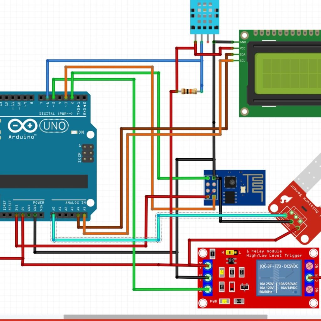
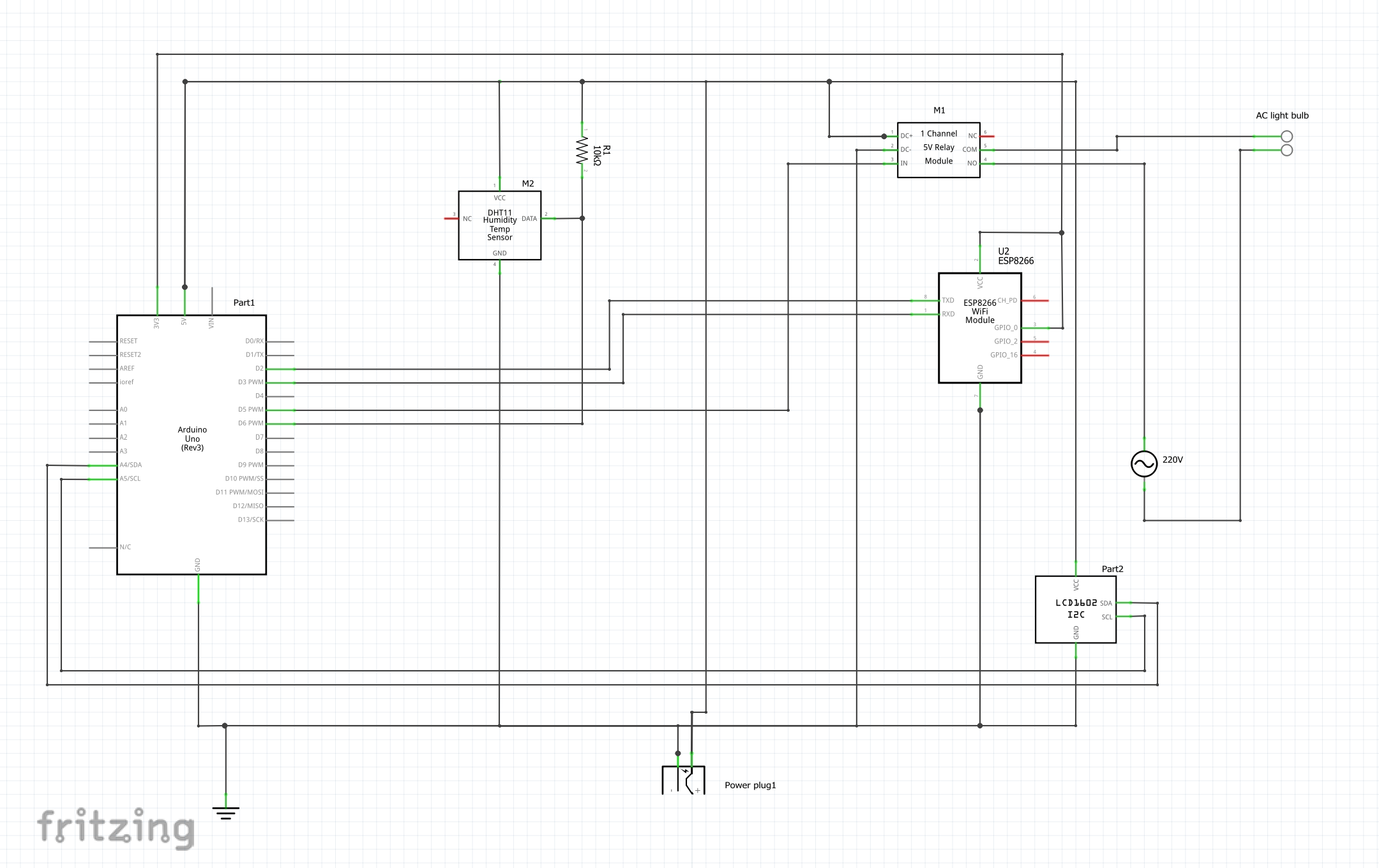
The Schematic Diagram for the IoT Based Temperature Control Poultry Farm Arduino Project
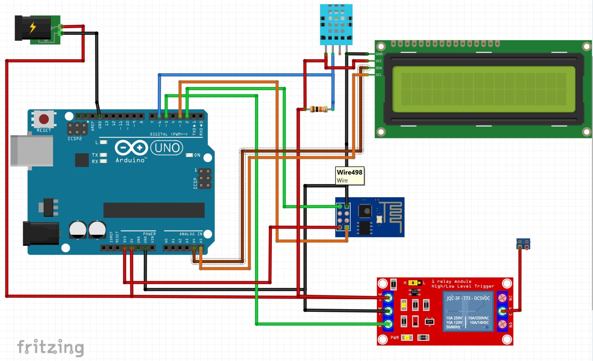
Circuit Connections And Explanation
We included an LCD for people who are closer to the project design who wants to see what the project is actually measuring at any particular time. This would help in knowing the accuracy of the project design too.
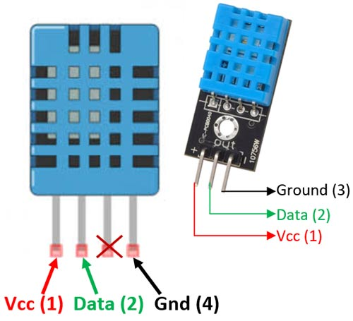
1. Connecting the DHT11 Sensor Module
- DHT11 Pinout:
- VCC: Power supply (typically 5V)
- DOUT: digital output voltage proportional to humidity and temperature
- GND: Ground
- Connections to Arduino Uno:
- VCC of DHT11 to 5V on Arduino Uno
- GND of DHT11 to GND on Arduino Uno
- OUT of DHt11 to D6 (digital input) on Arduino Uno
2. Connecting the ESP-01 WiFi Module
- ESP-01 Pinout:
- VCC: Power supply (3.3V)
- GND: Ground
- TX: Transmit data (UART)
- RX: Receive data (UART)
- CH_PD: Chip enable (connect to 3.3V)
- GPIO0: General-purpose input/output (connect to 3.3V for normal operation)
- GPIO2: General-purpose input/output (not used in this project)
- RST: Reset (not used in this project)
- Connections to Arduino Uno:
- VCC of ESP-01 to 3.3V on Arduino Uno (important: ESP-01 operates at 3.3V, not 5V)
- GND of ESP-01 to GND on Arduino Uno
- TX of ESP-01 to RX on Arduino Uno (through a voltage divider to step down 5V to 3.3V)
- RX of ESP-01 to TX on Arduino Uno (direct connection)
- CH_PD of ESP-01 to 3.3V on Arduino Uno
- GPIO0 of ESP-01 to 3.3V on Arduino Uno
3. Connecting the Relay Module
- Relay Pinout:
- VCC: Power supply (typically 5V)
- GND: Ground
- IN: Control signal from Arduino
- COM: Common terminal for switching
- NO: Normally open terminal
- NC: Normally closed terminal
- Connections to Arduino Uno:
- VCC of Relay to 5V on Arduino Uno
- GND of Relay to GND on Arduino Uno
- IN of Relay to any digital pin on Arduino Uno (e.g., D8)
- Connections for Control (AC light Bulb):
- Connect the controlled device (heater ) to COM and NO (for normally open configuration) or COM and NC (for normally closed configuration) on the relay module.
Programming the Project Design
Now, let us program the project design. we need some basic libraries for this project code to work on the Arduino IDE. We installed the DHT11 library using this link here. And since we finally decided to go with the RemoteXY app for the remote IOT monitoring, we equally installed their library from here.
#include <Adafruit_Sensor.h>
#include <DHT.h>
#include <DHT_U.h>
#include <Wire.h>
#include <LiquidCrystal_I2C.h>

/*
   -- Smart Farm --

   This source code of graphical user interface
   has been generated automatically by RemoteXY editor.
   */

// RemoteXY select connection mode and include library
#define REMOTEXY_MODE__ESP8266_HARDSERIAL_POINT

#include <RemoteXY.h>

// RemoteXY connection settings
#define REMOTEXY_SERIAL Serial
#define REMOTEXY_SERIAL_SPEED 115200
#define REMOTEXY_WIFI_SSID "DAMI FARM"
#define REMOTEXY_WIFI_PASSWORD "12345678"
#define REMOTEXY_SERVER_PORT 6377

// RemoteXY configurate
#pragma pack(push, 1)
uint8_t RemoteXY_CONF[] =
  { 255,1,0,47,1,85,0,8,45,2,
  2,1,37,28,16,8,20,31,26,12,
  2,32,31,31,79,78,0,79,70,70,
  0,67,0,1,40,98,6,1,59,61,
  7,31,26,101,67,0,1,48,98,6,
  1,73,61,7,2,26,101,67,0,1,
  56,98,6,1,88,61,7,13,26,101,
  129,0,6,2,89,16,5,5,55,10,
  2,83,109,97,114,116,32,70,97,114,
  109,0 };

// this structure defines all the variables of your control interface
struct {
    // input variable
  uint8_t SW1; // =1 if switch ON and =0 if OFF

    // output variable
  char SCREEN1[101];  // string UTF8 end zero
  char SCREEN2[101];  // string UTF8 end zero
  char SCREEN3[101];  // string UTF8 end zero

    // other variable
  uint8_t connect_flag;  // =1 if wire connected, else =0

} RemoteXY;
#pragma pack(pop)

/////////////////////////////////////////////
//           END RemoteXY include          //
/////////////////////////////////////////////

#define PIN_SW1 8

// what digital pin we're connected to
#define DHTPIN 6
#define DHTTYPE DHT11   // DHT 11

DHT dht(DHTPIN, DHTTYPE);
LiquidCrystal_I2C lcd(0x27, 16, 2); // Set the LCD address to 0x27 for a 16 chars and 2 line display

void setup() {
  RemoteXY_Init ();

  pinMode (PIN_SW1, OUTPUT);
  dht.begin();
  lcd.begin();
  lcd.backlight();
}

void soilMonitor() {
  // read the input on analog pin 0:
  int sensor = analogRead(A0);
  // Convert the analog reading (which goes from 0 - 1023) to a range (0 - 100):
  double TP = sensor * (100 / 1023.0);

  int soil = TP;
  if((soil < 40) || (soil == 40) && (RemoteXY.SW1 == 0)) {
    digitalWrite(PIN_SW1, HIGH);
    strcpy (RemoteXY.SCREEN3, "Pump in AUTO Mode");
  }
}

void loop() {
  RemoteXY_Handler ();
  soilMonitor();

  // read the input on analog pin 0:
  int sensor = analogRead(A0);
  // Convert the analog reading (which goes from 0 - 1023) to a range (0 - 100):
  double TP = sensor * (100 / 1023.0);

  int soil = TP;

  sprintf (RemoteXY.SCREEN1, "The Soil moisture reading is: %d", soil);

  if ((soil < 60) && (RemoteXY.SW1 ==1)) {
    digitalWrite(PIN_SW1, HIGH);
    strcpy (RemoteXY.SCREEN3, "Manual Override: Pump running");
  }
  if ((soil > 40) && (soil < 60) && (RemoteXY.SW1 == 0)) {
    digitalWrite(PIN_SW1, LOW);
    strcpy (RemoteXY.SCREEN3, "Pump is not running");
  }
  if((soil > 60) && (RemoteXY.SW1 ==1)) {
    digitalWrite(PIN_SW1, LOW);
    strcpy (RemoteXY.SCREEN3, "Warning!!! Farm Flooded, System AUTO Shut Off Pump");
  }
  if((soil > 60) && (RemoteXY.SW1 ==0)) {
    digitalWrite(PIN_SW1, LOW);
    strcpy (RemoteXY.SCREEN3, "Thanks, Farm Flooding Averted.");
  }

  float h = dht.readHumidity();
  // Read temperature as Celsius (the default)
  float t = dht.readTemperature();
  int Temp = t;
  int Hum = h;

  // Check if any reads failed and exit early (to try again).
  if (isnan(h) || isnan(t)) {
    strcpy (RemoteXY.SCREEN3, "Warning!!! Failed to read from DHT sensor!");
    return;
  }

  sprintf (RemoteXY.SCREEN2, "Farm Humidity is: %d, Temperature is: %d'C", Hum, Temp);

  // Display the temperature and humidity on the LCD
  lcd.setCursor(0, 0);
  lcd.print("Temp: ");
  lcd.print(Temp);
  lcd.print((char)223); // Degree symbol
  lcd.print("C  ");

  lcd.setCursor(0, 1);
  lcd.print("Humidity: ");
  lcd.print(Hum);
  lcd.print("%");
}
Explanation of the Code
- Library Addition:
#include <Wire.h>#include <LiquidCrystal_I2C.h>
- LCD Initialization:
LiquidCrystal_I2C lcd(0x27, 16, 2);
0x27and sets it up for 16 columns and 2 rows. - LCD Setup:
lcd.begin();lcd.backlight();
setup()function. - LCD Display:
- The temperature and humidity readings are displayed on the LCD using
lcd.setCursor()andlcd.print()functions.
- The temperature and humidity readings are displayed on the LCD using
Project System Design Expansion
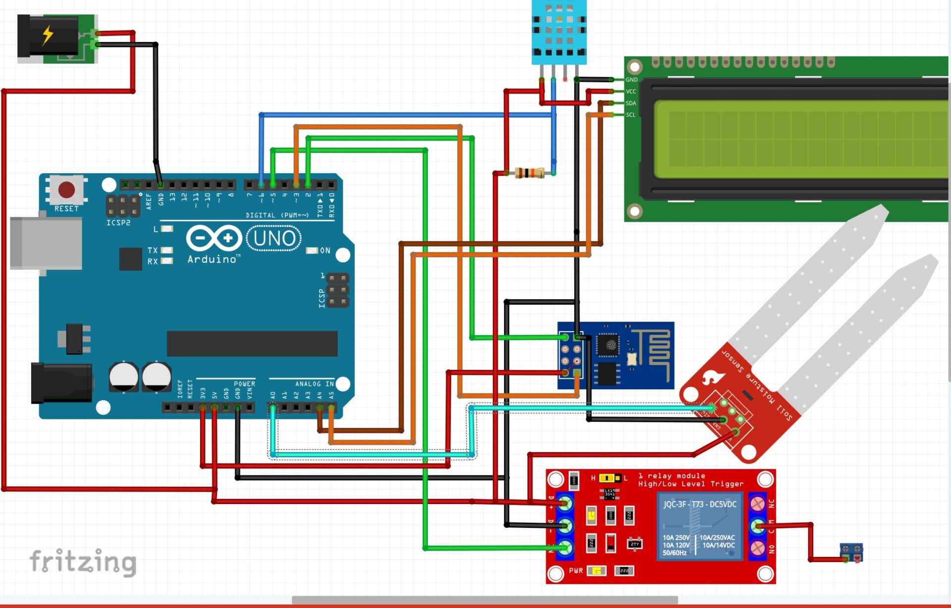
To account for some changes, we had to incorporate an additional module to the schematic diagram as shown above. We reasoned about watering and supplying water to the poultry bird for drinking. And we wanted to remotely do this, and also ensure we know the level of water left in their drinking bowl.
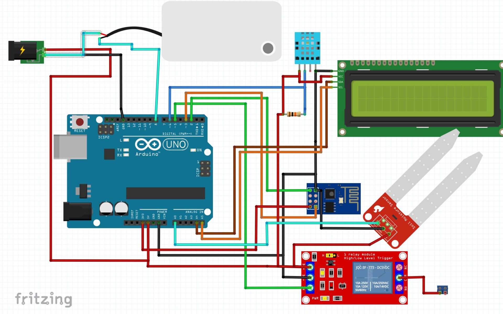
We used a soil moisture meter or sensor module to achieve this feat. This will tell us what the level of the drinking water is at any particular time. The program code allowed us to control it in two modes: the automatic mode and the user mode. The Automatic mode is when the system regulate the feeding water to the poultry birds by itself and the user mode is where the user does the turning on or off of the pump supplying water to the bird’s drinking bowl.
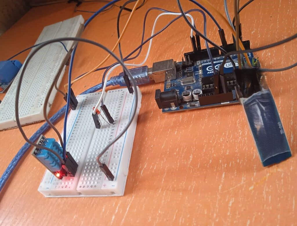
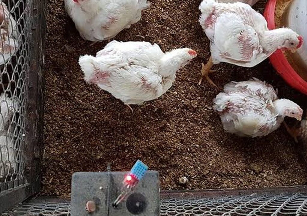
Integration and Testing
Real Life Applications and Importance Benefits of the Project Design
Putting such a system in place emphasizes how crucial it is to incorporate contemporary technology into conventional farming methods in order to create sustainable and effective agricultural operations. By using this robust and scalable Android platform-based solution, poultry producers can better manage temperature and oversee operations to accommodate their changing needs.
Other functions include:
- Enhanced Monitoring: Real-time temperature monitoring enables proactive management of poultry farm conditions.
- Remote Accessibility: Accessibility via Android platform allows farm managers to monitor and control temperature parameters remotely, improving operational efficiency.
- Data Logging and Analysis: The system can log temperature data over time, facilitating historical analysis and trend identification for informed decision-making.
Conclusion
An important development in agricultural technology is the temperature monitoring system for chicken farms that is based on the IoT smart phone platform. Poultry producers can attain accurate temperature and humidity control and monitoring capabilities by utilizing an Arduino Uno, as well as drinking water for the birds by using the DHT11 sensor, the moisture sensor and an ESP-01 WiFi module. In addition to improving the welfare of poultry birds, this maximizes farm output and streamlines operations.
Let us know if you replicated this project design in the comment section below. We hope to hear from you soon. Good luck!
Read Also…
IoT Pump Control for Efficient Irrigation Systems
Frequently asked questions (FAQs) related to the project
1. What is the purpose of this Smart Poultry Farm project?
- Answer: The Smart Poultry Farm project is designed to monitor soil moisture, temperature, and humidity levels in a farm environment. It automates irrigation by controlling a water pump based on soil moisture readings and provides real-time data on farm conditions via an LCD display and a mobile interface using RemoteXY.
2. How does the soil moisture sensor work in this project?
- Answer: The soil moisture sensor measures the water content in the feeding bowl by detecting the electrical resistance between its probes. The analog readings from the sensor are converted into a percentage value, which the system uses to determine whether the feeding is dry, adequately moist, or flooded. Based on these readings, the system automatically turns the water pump on or off from the supply reservoir through the DC pump connected to an external relay or NPN transistor.
3. What role does the DHT11 sensor play in this project?
- Answer: The DHT11 sensor is used to measure the temperature and humidity levels in the farm environment. The data collected by this sensor is displayed on an LCD screen and sent to a mobile device via the RemoteXY app. This information helps farmers monitor environmental conditions that could affect bird’s growth and welfare.
4. How is the water pump controlled in this project?
- Answer: The water pump is controlled using a relay connected to the Arduino. The relay acts as a switch that the Arduino can turn on or off based on moisture meter readings. If the moisture meter is below a certain threshold, the pump is activated to water the drinking bowl. If the water bowl is sufficiently moist or flooded, the pump is turned off to prevent overwatering.
5. How can I view the real-time data and control the system remotely?
- Answer: The project uses the RemoteXY platform, which allows you to connect your Arduino to a mobile device over Wi-Fi. The real-time data, including soil moisture, temperature, and humidity, can be viewed on your smartphone, and you can control the water pump manually through the app. The LCD screen also displays this data locally, providing both remote and on-site monitoring options.

