In the modern age, home automation is no longer just a luxury; it’s a necessity for enhancing safety, convenience, and energy efficiency. One of the more innovative and practical DIY projects that integrates automation with safety is an automated window system with Arduino. This system is designed to automatically close your windows when it detects rain, smoke, or harmful gases, and reopen them when the environment is clear and safe. Whether you’re a seasoned maker or just starting your journey into the world of electronics, this project is an excellent way to improve your home while learning valuable skills.
In this comprehensive guide, we’ll walk you through the process of creating this automated window system. We’ll cover everything from understanding the components to wiring and coding, and finally, testing and optimizing the system for real-world use. By the end of this post, you’ll have a fully functional, smart window automation system that enhances your home’s safety and provides you with a sense of accomplishment.
Introduction to Smart Window Automation
Smart home technology is transforming the way we live, offering solutions that make our lives easier and safer. One such innovation is the automated window system. This system not only provides convenience by automating the opening and closing of windows but also serves as a crucial safety feature. Imagine a scenario where you’re away from home, and suddenly it starts raining. With a smart window system, there’s no need to rush back home; the windows will close automatically, protecting your home from water damage.
Moreover, the system can detect dangerous smoke or harmful gases, automatically closing the windows to prevent these hazards from entering your living space. This feature is particularly useful in preventing smoke from wildfires, gas leaks, or other similar dangers. Once the environment is safe, the windows reopen, ensuring your home remains well-ventilated.
Building this system yourself not only saves money but also gives you control over customization. You can tailor the system to your specific needs, and the knowledge gained from this project can be applied to other DIY home automation projects.
Understanding the Components Needed for the Automated Window System with Arduino Project
Before diving into the build process, it’s essential to understand the components that make up the system. Each component plays a critical role in ensuring the system functions correctly.
Arduino Uno
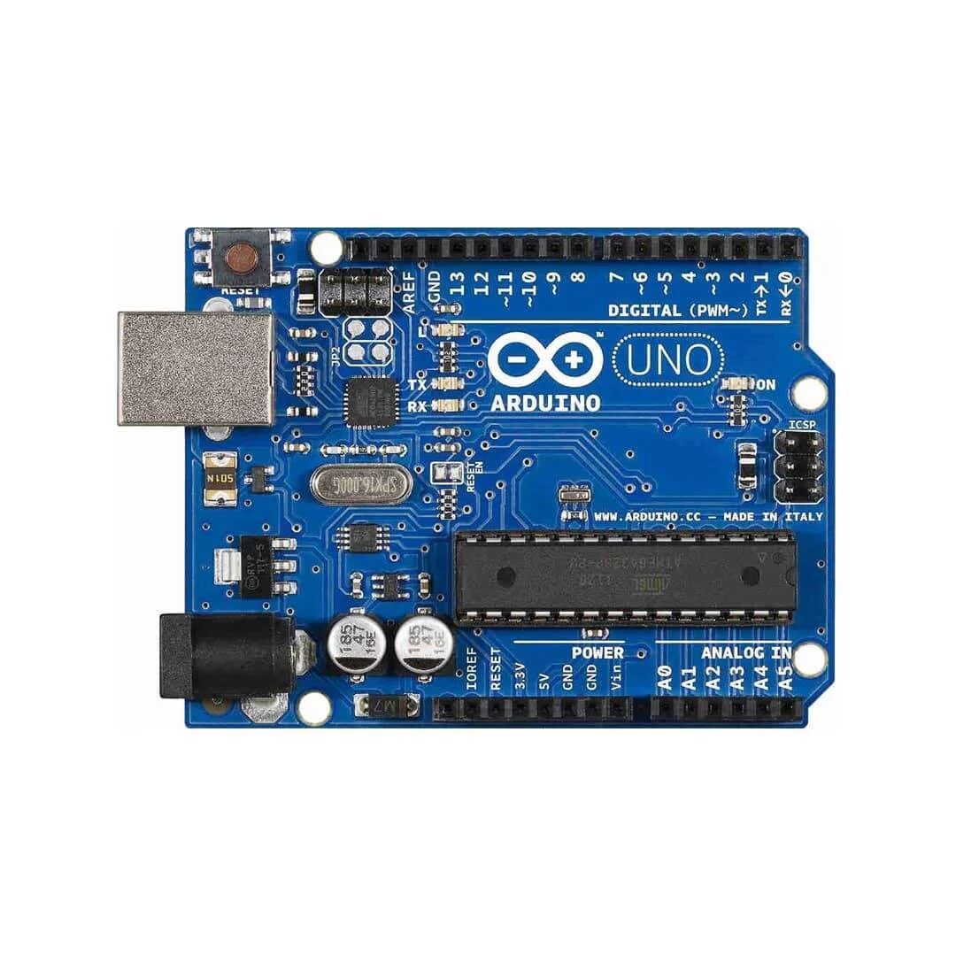
The Arduino Uno is the brain of this project. It’s a microcontroller board that processes inputs from various sensors and sends commands to the actuators to open or close the window. The Arduino Uno is user-friendly and has a vast community support, making it ideal for beginners and experienced makers alike.
Rain Sensor
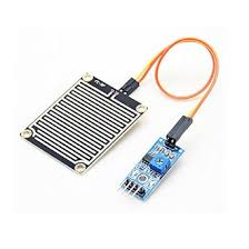
The rain sensor detects moisture and sends a signal to the Arduino to close the window when it starts raining. This sensor is crucial for protecting your home from water damage during unexpected showers.
Smoke Detector Sensor
The smoke detector sensor is responsible for sensing dangerous smoke inside the room. If smoke is detected, the Arduino will command the actuators to close the window, preventing smoke from entering and protecting your home from potential fire hazards.
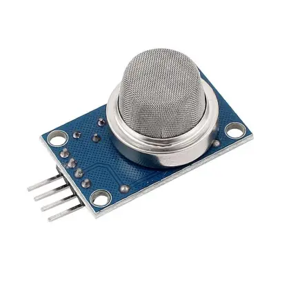
Gas Sensor (MQ-2)
The MQ-2 gas sensor detects harmful gases such as carbon monoxide, methane, and LPG. If these gases are detected, the system will automatically close the window to prevent these toxic substances from entering your living space.
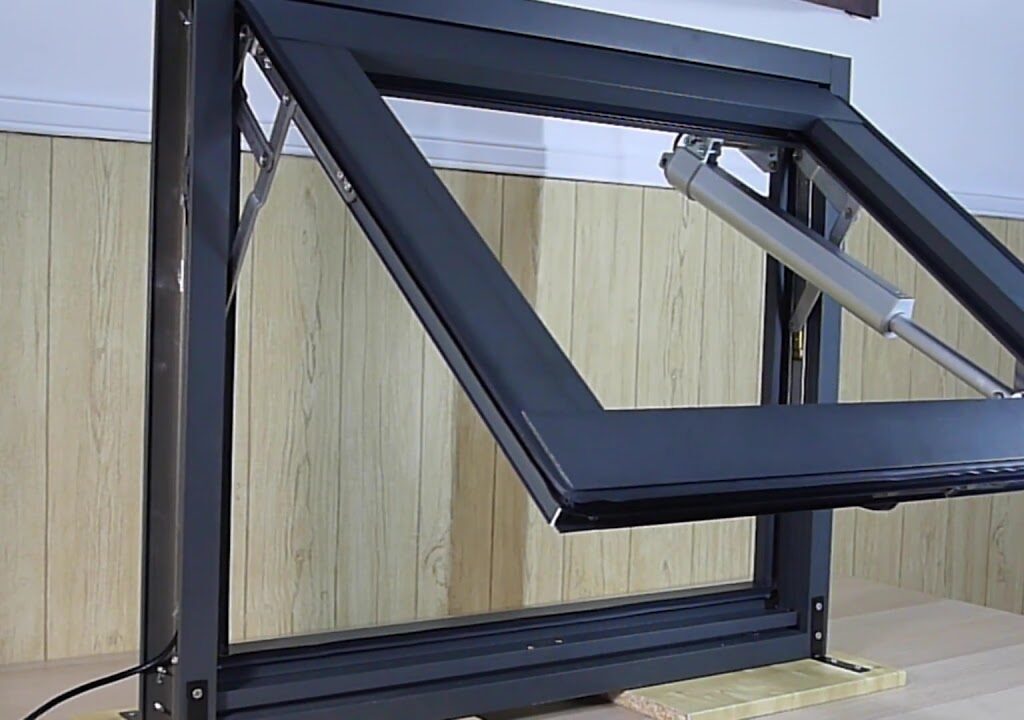
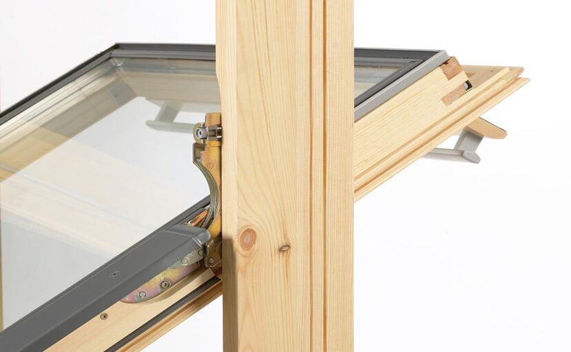
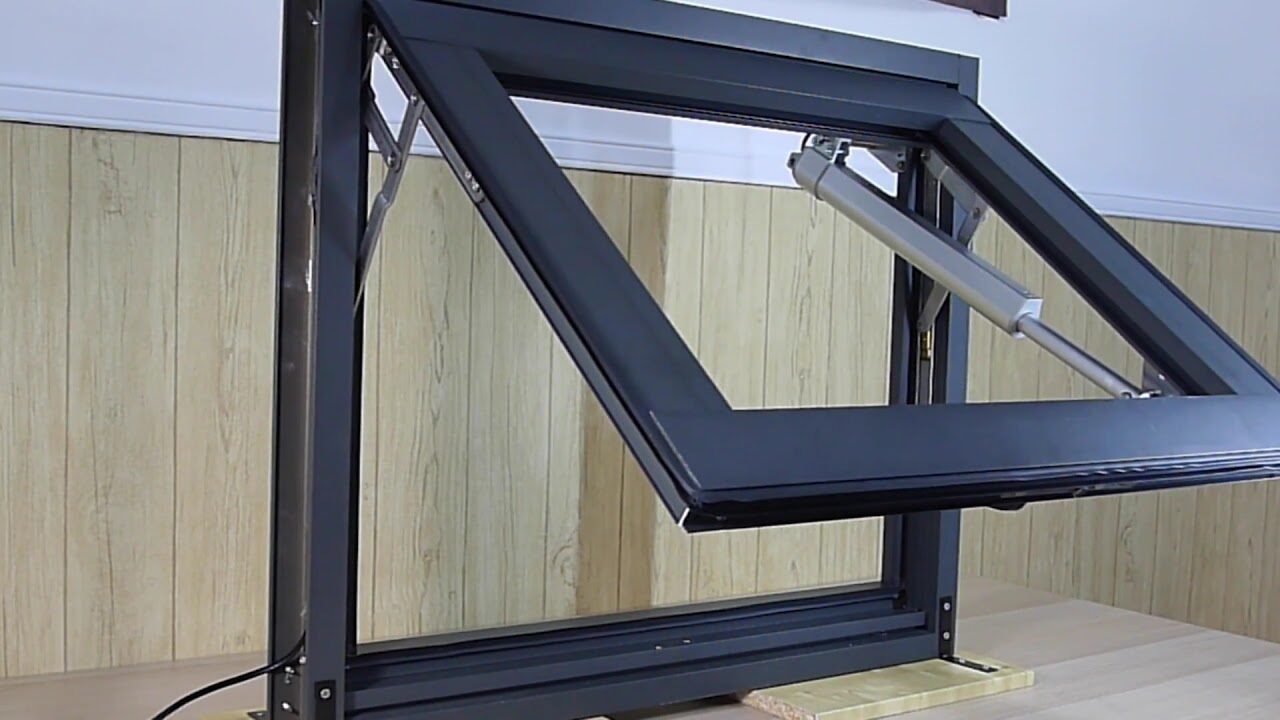
Actuators (Servos or Motors)
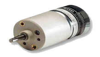
Actuators are the mechanical components that physically open and close the window. They receive signals from the Arduino and convert them into motion. Depending on your window’s size and type, you can choose between servos or motors.
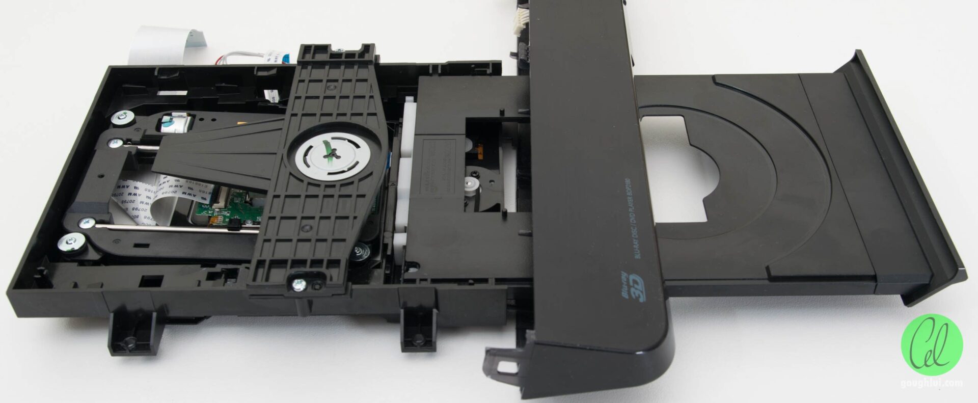
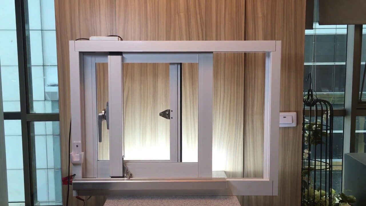
For this project design, we used a 5V DC motor which we pull off from the DVD tray mechanism of an old DVD player. We built a house model/home model that focused on bringing out the Window side view more. And the windows were constructed with the sliding part of these mechanisms.
L293D Motor Driver IC and Motor Module
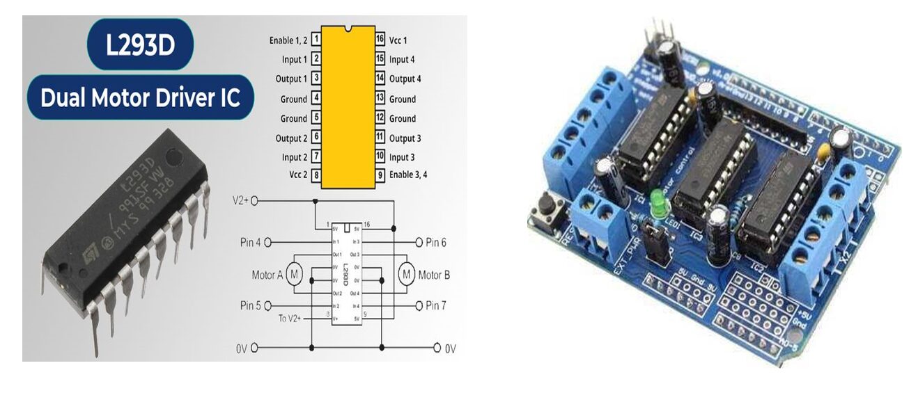
The module version would have been the best to use since it offer a seamless plug and play use. However, the cost of this module is also an important factor to consider. To solve this, we just the driver IC itself. It is much cheaper and offer the same solution. With a little bit of configuration and some other discrete components connected to it according to the schematic diagram you will find below, you can be up and running in no time. It allows the Arduino to drive the slider control forward and backwards, enabling the opening and closing of the window.
Power Supply
The power supply provides the necessary power to the entire system, including the Arduino, sensors, and actuators. It’s important to choose a power supply that matches the voltage and current requirements of your components.
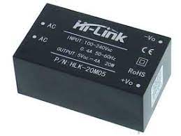
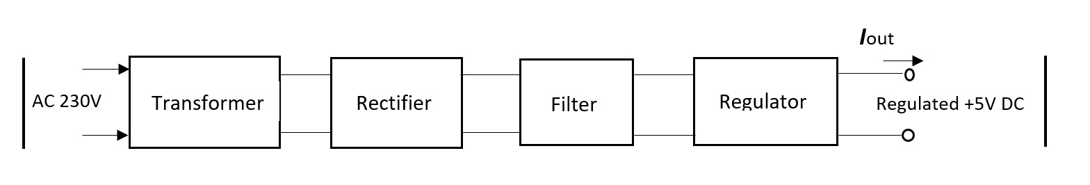
The above block diagram shows the linear power supply breakdown that could be used for this project. You can used use a power supply module of your choice to achieve this. The system requires 5V to run and you can give the DC motor up to 12V. However, the higher the voltage, the faster it runs. To ensure the demonstration is observed, you can use a 5V supply that is packing a current rating of 2A or above. The Hi-Link power supply shown above is an intelligent power supply and can also serve. But it is pricey.
Read Also DIY Non-Invasive Blood Pressure and Cholesterol Level Monitoring
Circuit Diagram of Automated Window System With Arduino
The Linear Power Supply Circuit Diagram
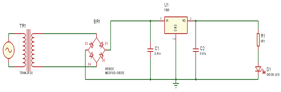
Explanation of the Linear Power Supply Diagram
The bridge rectifier, which is used to convert the ac supply to dc, receives this AC voltage that comes in from the step down transformer. The rectified voltage that emerges from the rectifier is a DC voltage that pulses and has a significant amount of ripple. However, we are looking for a pure DC waveform devoid of ripples, not something like this. Thus, a filter is applied.When the negative part of diode D1 and negative part of diode D2 are connected together it gives a positive (+) AC input, while when the positive part of diode D3 and positive part of diode D4 are connected together it gives a negative (-) AC input to the power supply unit.
The pulsating DC voltage which still contains some AC voltage flows to the capacitor which is used to smoothing the ripples from the rectifier output. The capacitors used here is 1000µF and 0.1 µF respectively.
In order to ensure that the ripple from the rectifier output is entirely rectified by obstructing any trace of AC that may have escaped the bridge rectifier during rectification, the power supply unit uses two capacitors, C1 and C2. The capacitor C1’s positive leg is connected to the positive side of the bridge rectifier, and its negative side is grounded. This circuit makes use of an LM7805 voltage regulator. The output of the LM7805 is 5V. Pin 2 of the voltage regulator is grounded, Pin 3 is linked to the positive of another capacitor, C2, (0.1µF), and Pin 1 of the voltage regulator is connected to the positive leg of C1 (1000µF). When the mains are powered on, current flows through the power supply circuit, the current that flows to the LM7805 regulator will give an output of 5V.
Control Unit of the Automated Window system Project Design
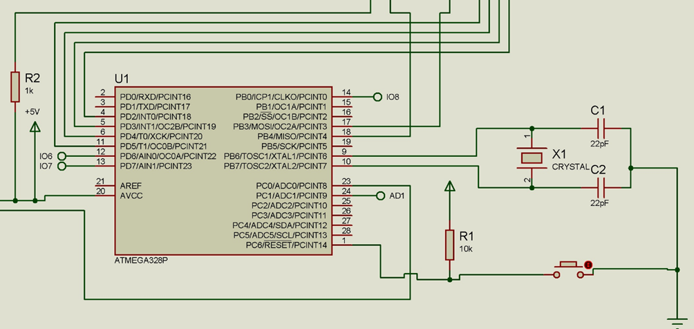
In other to further save cost, we had to build our own Arduino Uno using the Arduino Standalone version circuit diagram shown above. It is more or less an Arduino breakout board.
The microcontroller, which serves as the project’s “brain,” is the control unit in the design. The project’s behavior or functionality is determined by the microcontroller, Atmega328P-PU, which was used. Because of the Arduino IDE’s exceptionally efficient code, the Atmel chip can operate with a lot less program memory than its larger competitors. They may be programmed to carry out a variety of tasks, including managing a generation line. As a result, the project is even more manageable and less tiresome. It has a lower price and a faster clock speed.
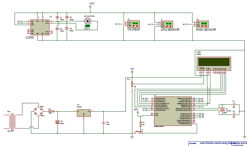
The above schematic diagram shows the overall connection of the project design. We included a temperature sensor to check for the temperature and also a display module the 1602 LCD module to display the readings of the project design.
Programming the Project Design
#include <LiquidCrystal.h>

//include the oneWire lib
#include <OneWire.h>
//include the Dallas temp lib
#include <DallasTemperature.h>

// Data wire is plugged into pin 2 on the Arduino
#define ONE_WIRE_BUS A1

  int windowForward = 10;
  int windowBackward = 13;


int switch1 = 6;
int switch2 = 7;

//State the toxidity level
 int toxicLevel = 350;

// analog pin 0 = sensor  i/p
int rainSensePin= A0;

// current counter - goes up by 1 every second while sensing
int curCounter= 0;

//declear the i/p for smoke detection
int smokeSense = A2;

// Setup a oneWire instance to communicate with any OneWire devices connected
OneWire oneWire(ONE_WIRE_BUS);

// Pass our oneWire reference to Dallas Temperature.
DallasTemperature sensors(&oneWire);
// initialize the library by associating any needed LCD interface pin
//state which pin of the LCD is connected
LiquidCrystal lcd(12, 11, 5, 4, 3, 2);

void setup(){
  Serial.begin(9600);
  sensors.begin();
  pinMode(windowForward, OUTPUT);
  pinMode(windowBackward, OUTPUT);
  pinMode(switch1, INPUT);
  pinMode(switch2, INPUT);
  lcd.begin(16, 2);
  // Display a welcome message
  lcd.setCursor(0, 0);
  lcd.print("AUTOMATIC WINDOW");
  delay(500);
  lcd.setCursor(0, 1);
  lcd.print(" CONTROL SYSTEM: ");
  delay(2000);
  lcd.setCursor(0, 0);
  lcd.print("1> RAIN-SENSING,");
  delay(1500);
  lcd.setCursor(0, 1);
  lcd.print("2> TEMP-SENSING,");
  delay(1000);
  lcd.setCursor(0, 0);
  lcd.print("2> TEMP-SENSING,");
  delay(1000);
  lcd.setCursor(0, 1);
  lcd.print("3> SMOKE-SENSING");
  delay(2000);
  lcd.setCursor(0, 0);
  lcd.print("  DESIGNED BY:  ");
  delay(1000);
  lcd.setCursor(0, 1);
  lcd.print("OMOLOLA  ADEMOLA");
  delay(2000);
  }

void loop(){
sensors.requestTemperatures();
Serial.print("  Temperature is: ");
Serial.print(sensors.getTempCByIndex(0));
Serial.println("'C");
float roomTemp = sensors.getTempCByIndex(0);
  lcd.setCursor(0, 0);
  lcd.print("ROOM TEMP:");
  lcd.setCursor(9, 0);
  lcd.print(roomTemp);
  lcd.setCursor(14, 0);
  lcd.print("'C");


int rainSenseReading = analogRead(rainSensePin);
Serial.print("NOw rain ");
Serial.println(rainSenseReading);


//begin reading from smoke sensor
int readSmoke = analogRead(smokeSense);
Serial.print(" Now Smokereading: ");
Serial.println(readSmoke);
delay(500);

  int sense1 = digitalRead(switch1);
  int sense2 = digitalRead(switch2);

   if( sense2 == LOW) {
   if ((rainSenseReading < 350) || (readSmoke >= 280)){
     digitalWrite(windowForward, HIGH);
    digitalWrite(windowBackward, LOW);
    delay(300);
    lcd.setCursor(0, 1);
    lcd.print("WINDOW      ");
    lcd.setCursor(7, 1);
    lcd.print("OPENED    ");
   }
   }
    else if( sense2 == HIGH){
    if ((rainSenseReading < 350) || (readSmoke >= 280)){
    digitalWrite(windowForward, LOW);
    digitalWrite(windowBackward, LOW);
    delay(300);

    }

   }


if( sense1 == LOW) {
if((roomTemp > 40.00) && (rainSenseReading > 350) && (readSmoke <= 280) )
{
    digitalWrite(windowForward, LOW);
    digitalWrite(windowBackward, HIGH);
    delay(300);
    lcd.setCursor(0, 1);
    lcd.print("WINDOW      ");
    lcd.setCursor(8, 1);
    lcd.print("CLOSED    ");

  }
}
else if( sense1 == HIGH)
{
  if((roomTemp > 40.00) && (rainSenseReading > 350) && (readSmoke <= 280))
  digitalWrite(windowForward, LOW);
  digitalWrite(windowBackward, LOW);
  delay(300);

}
}
Explanation of Arduino Source Code
The oneWire library (from the Maxim Company) was included from the source code at lines 1 and 2 so that the IDE could understand the remaining syntax. The DS18B20 can determine the temperature in Celsius and Fahrenheit scales, respectively, thanks to the special library called Dallas Temperature, which is located at line 3. This is accomplished with a unique built-in algorithm. Any other IC linked to the Bus or wire could potentially be accessed by the application thanks to line 10. not limited to Onewire ICs only. Line 13 instructs the DallasTemp lib to use its built-in algorithm to return the temperature findings by reading off signals from which ICs. The temperature sensor in this instance was identified as oneWire.
At Line 15, the function setup started the sensor at line 18. To obtain a real time temperature reading, the sensing of the temperature has to be taken continuously; at 30 code line where it prints out the temperature in degree Celsius in the function loop, it repeats the codes continuously depending of the pause time known as delay.
Testing and Calibration
The project worked as programed and was tested when we dropped water on the top of the sensor, thereby simulating rainfall. Also we tested the gas sensors using burning paper, and this trigger the window to automatically close. All these while, we can measure and display the temperature of the surroundings of the project design on the LCD screen.
Conclusion
We have successfully designed and implemented the project design. We have tested and found it working within the scope of the design, and we could also recommend that anyone who wants to replicate the project could expand on the ideas perhaps by including other functionalities to it. However, if you were successful in building this project following this post, leave us a comment below.
FAQs on DIY Home Safety: Create an Automated Window System with Arduino for Rain, Smoke, and Gas Protection
1. How does the Arduino-based automated window system enhance home safety?
The Arduino-based automated window system enhances home safety by automatically closing your windows when it detects rain, smoke, or harmful gases. This prevents potential hazards from entering your home, such as water damage, smoke inhalation, or exposure to toxic gases. Once the environment is safe, the system reopens the windows, ensuring that your home remains protected and well-ventilated.
2. What are the main components needed for this DIY automated window system?
The main components required for this DIY automated window system include an Arduino Uno microcontroller, a rain sensor to detect moisture, a smoke detector sensor to monitor for smoke inside the room, a gas sensor (such as the MQ-2) to detect harmful gases, actuators (like servos or motors) to open and close the window, a relay module to control the actuators, and a power supply to power the entire system.
3. Can this automated window system be expanded to control multiple windows?
Yes, this automated window system can be expanded to control multiple windows by adding additional sensors and actuators for each window. The Arduino can be programmed to monitor multiple sensor inputs and control multiple actuators simultaneously, allowing you to automate the operation of several windows throughout your home.
4. How do I test the Arduino-based automated window system before installation?
Before installing the system on a real window, it’s important to test it on a small scale. You can simulate different conditions such as rain, smoke, and harmful gases to see how the system responds. Ensure that the sensors detect the appropriate conditions and that the actuators correctly open and close the window. Adjust the code and calibrate the sensors if necessary to achieve reliable performance.
5. What are the energy efficiency benefits of using this automated window system?
The automated window system helps improve energy efficiency by maintaining a stable indoor temperature. When it detects rain, the system automatically closes the windows to prevent cold air from entering, reducing the need for heating. Similarly, by closing the windows during hazardous gas detection, it helps maintain air quality and reduces the load on air purification systems, contributing to overall energy savings.

