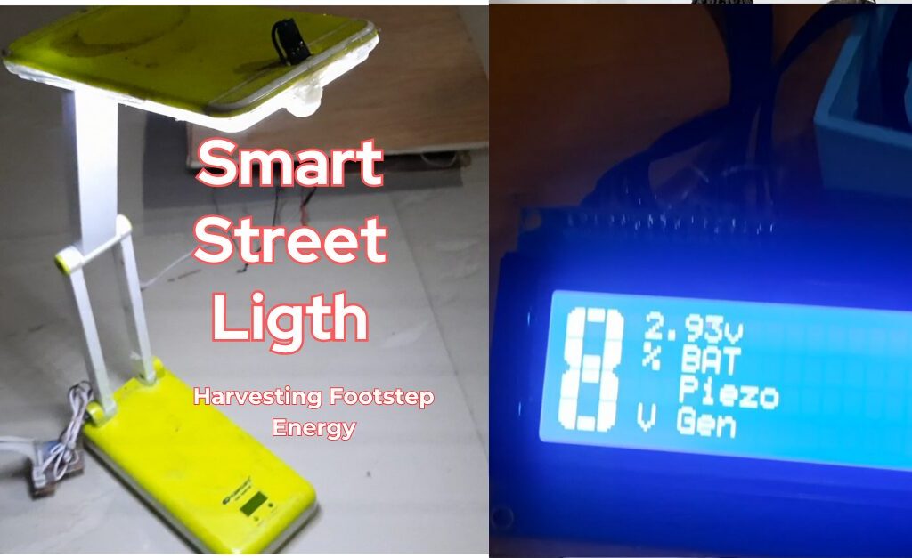
Smart street lights are a revolutionary step toward energy efficiency, combining technology, sustainability, and innovation. Imagine a street light that illuminates brightly only when it senses motion, conserves energy by dimming when no one is around, and recharges its batteries using the power of footsteps! This project tutorial dives into the design, components, working principles, and benefits of a Smart Street Light System Project that involves harvesting footstep energy built using simple but innovative tools.
Let’s explore the details of how this energy-saving street light works and why it is a perfect solution for sustainable urban lighting.
What is a Smart Street Light System?

A smart street light system uses intelligent control systems to provide efficient lighting. Unlike traditional street lights that remain fully illuminated all night, this design adjusts its brightness based on motion detection, significantly saving energy. It also features an innovative power solution that recharges the batteries using footstep pressure energy via a PZT transducer array.
Read Also: How to Build A Motorized Curtain System using DC Motor, Push Buttons, and Arduino Uno
Components Used in the Smart Street Light Project
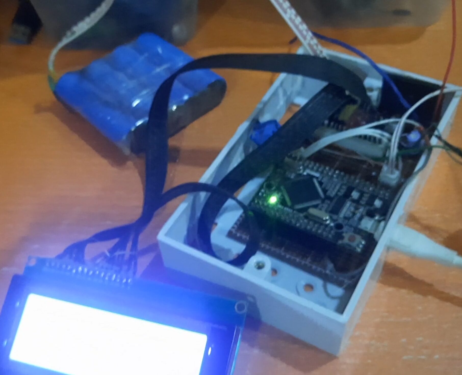
To understand how this project works, here are the primary components used:
- Arduino Mega (Compact Type): The brain of the project that processes all inputs and controls the LED arrays.
- LED Arrays: Sourced from an old Lontor rechargeable lamp, these LEDs provide efficient illumination.
- LDR (Light Dependent Resistor): Detects daylight to determine when to turn the lights on or off.
- PIR Motion Sensor: Senses motion to increase illumination to full brightness.
- Switch: Allows manual control to turn the system off.
- LiPo Batteries: Four 4.2V 3800mAH rechargeable batteries supply power to the system.
- PZT Transducer Array: Converts footstep pressure into electrical energy to recharge the batteries.
- Battery Management System (BMS): Ensures safe charging and discharging of LiPo batteries.
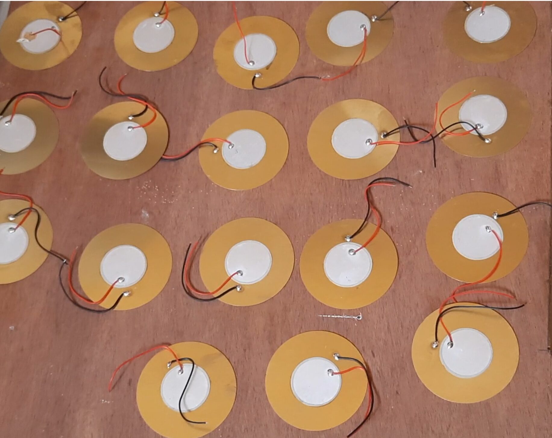
Each component plays a vital role in ensuring the project works efficiently and sustainably.
Read Also: Digital Temperature Monitor Using LM35 Sensor and Arduino
How the Smart Street Light Works
1. Night Detection with LDR
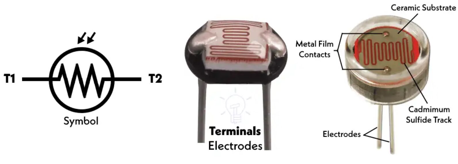
The LDR acts as a sensor to detect daylight levels. When it gets dark, the Arduino Mega activates the LED arrays at a low illumination level to save power.
Read Also: How to Build An IoT Smart Electricity Meter with Real-Time Monitoring
2. Motion Detection with PIR Sensor

At night, the PIR motion sensor continuously monitors its surroundings for movement. When a person or vehicle passes by:
- The PIR sensor detects motion.
- The Arduino signals the LED arrays to increase brightness to full illumination.
- After a few seconds of inactivity, the LEDs return to low illumination mode.
This ensures the street light provides full brightness only when needed, saving a significant amount of energy.
Read Also: How Long Would It Take a Hacker to Brute Force Your Password?
3. Power Supply with LiPo Batteries

The system is powered by four 4.2V 3800mAH LiPo batteries connected in parallel. These batteries are lightweight, efficient, and rechargeable, making them perfect for portable energy solutions.
4. Charging Batteries with PZT Transducer Array
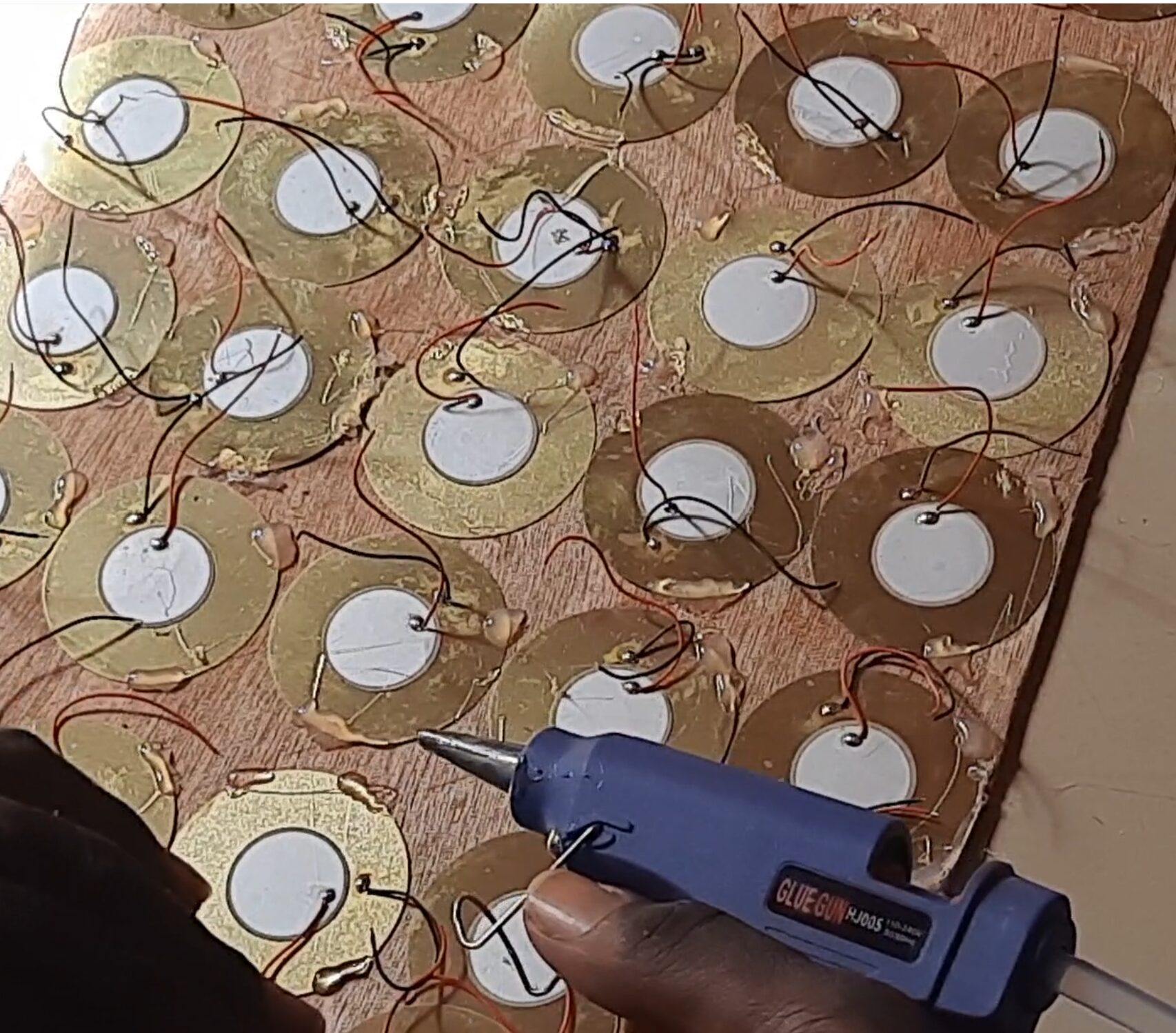
The most innovative part of this project is the charging system. A PZT transducer array converts footstep pressure into electrical energy:
- Footsteps generate mechanical pressure on the PZT transducers.
- This mechanical energy is converted into electrical energy.
- The energy directly recharges the LiPo batteries, ensuring a sustainable power source.
See Also: IoT-Enabled Asset Tracking Solutions in Industrial Settings
5. Manual Control with Switch
A manual switch allows users to turn off the street light system completely, providing additional control and saving power when the system is not in use.
Benefits of this Smart Street Light System
1. Energy Efficiency

By dimming the lights when no motion is detected, the system reduces unnecessary power consumption.
2. Sustainability
The use of PZT transducers to recharge batteries harnesses renewable energy from footsteps, making the system eco-friendly.
3. Cost-Effective
Reduced energy consumption translates to lower electricity costs, making this system economically viable for urban lighting.
4. Extended Battery Life
The system’s design ensures batteries are used efficiently, prolonging their lifespan.
5. Versatility
The project can be implemented in streets, pathways, parks, and even remote areas where energy conservation is critical.
Step-by-Step Guide to Building the Smart Street Light
The Schematic Diagram

Explanation of Schematic Diagram
This is full schematic diagram of the footstep energy generation. We used the Arduin mega (compact type) here. You can download the code from my GitHub page here. Here is an overview of the steps involved in building this smart system:
Step 1: Gather Components
Ensure you have the Arduino Mega, LDR, PIR sensor, LED arrays, LiPo batteries, PZT transducers, and other necessary components.
Step 2: Connect the LDR
- Connect the LDR to one of the analog pins of the Arduino.
- Program the Arduino to read light intensity and turn on the LEDs when it gets dark.
Step 3: Integrate the PIR Motion Sensor
- Connect the PIR motion sensor to a digital input pin of the Arduino as shown in the schematic diagram above.
- Write a code that detects motion and increases LED brightness for a set period.
Step 4: Set Up the LED Arrays
- Connect the LED arrays to the Arduino through appropriate resistors.
- Test the LEDs to ensure they work in both low and full brightness modes.
Step 5: Rechargeable Battery Integration
- Connect the LiPo batteries to the power supply system.
- Use a Battery Management System (BMS) to prevent overcharging or over-discharging.
Step 6: Install the PZT Transducer Array
- Place the PZT transducers in a setup where footsteps will generate pressure.
- Connect the transducers to the batteries to ensure they recharge efficiently.
Programming the Arduino Mega
// include the library code:
#include <LiquidCrystal.h>
#include <EEPROM.h>
#include <BigCrystal.h>
#include <BigFont.h>
#include <SoftwareSerial.h>

// initialize the library with the numbers of the interface pins
LiquidCrystal lcd(9, 13, 22, 25, 27, 29);
BigCrystal bigCrystal(&lcd);

int volt;
float voltage1;

float low = 3.2;
float full = 10.0;
//for the ESP-01
#define gpio0 18  //used for software serial
#define gpio1 28
#define gpio2 20  //used for software serial
#define gpio3 30
//the serial comm.
SoftwareSerial arduino(gpio2, gpio0);
//for LDR
#define ldrPin A2
//for pirSensor
#define pirSensorPin 7
//for the transistor
#define transistorBase 11

// Define analog input for battery
#define ANALOG_IN_PIN A1
// Floats for ADC voltage & Input voltage
float adc_voltage = 0.0;
float in_voltage = 0.0;
// Floats for resistor values in divider (in ohms)
float R1 = 32380.0;
float R2 = 11760.0;
// Float for Reference Voltage
float ref_voltage = 5.0;
// Integer for ADC value
int adc_value = 0;

//define parameters for piezo generator
float R3 = 30000.0;
float R4 = 7500.0;
#define ANALOG_IN_PIN1 A0
// Floats for ADC voltage & Input voltage
float adc_voltage1 = 0.0;
float in_voltage1 = 0.0;
// Float for Reference Voltage
float ref_voltage1 = 5.0;
// Integer for ADC value
int adc_value1 = 0;
int readButton;


void setup() {
  // set up the LCD's number of columns and rows:
  lcd.begin(20, 4);
  Serial.begin(9600);
  arduino.begin(115200);
  //declare the inputs and outputs
  pinMode(transistorBase, OUTPUT);
  pinMode(pirSensorPin, INPUT);
  pinMode(ldrPin, INPUT);
  pinMode(gpio1, INPUT);
  pinMode(gpio3, INPUT);
  //write a welcome msg on lcd
  lcd.setCursor(2, 0);
  lcd.print("...WELCOME...");
  lcd.setCursor(3, 1);
  lcd.print("MR. BUKOLA ");
  delay(3000);
  lcd.clear();
  lcd.setCursor(4, 0);
  lcd.print("FOOT-STEP");
  lcd.setCursor(2, 1);
  lcd.print("PIEZOELECTRIC");
  lcd.setCursor(3, 2);
  lcd.print(" GENERATOR");
  lcd.setCursor(3, 30);
  lcd.print("  PROJECT");
  delay(3000);
  lcd.clear();
  for (int x = 0; x < 16; x++) {
    lcd.setCursor(0, 0);
    lcd.print("Checking Battery  ");
    lcd.setCursor(x, 1);
    lcd.print("*");
    delay(200);
  }
  lcd.clear();
}

float readBatteryVoltage() {
  // Read the Analog Input
  adc_value = analogRead(ANALOG_IN_PIN);

  // Determine voltage at ADC input
  adc_voltage = (adc_value * ref_voltage) / 1024.0;

  // Calculate voltage at divider input
  in_voltage = adc_voltage * (R1 + R2) / R2;

  // Print results to Serial Monitor to 2 decimal places
  // Serial.print("Input Voltage = ");
  // Serial.println(in_voltage, 2);
  return in_voltage;
}

float readPiezoGenVoltage() {
  // Read the Analog Input
  adc_value1 = analogRead(ANALOG_IN_PIN1);

  // Determine voltage at ADC input
  adc_voltage1 = (adc_value1 * ref_voltage1) / 1024.0;

  // Calculate voltage at divider input
  in_voltage1 = adc_voltage1 * (R3 + R4) / R4;

  // Print results to Serial Monitor to 2 decimal places
  // Serial.print("Input Voltage = ");
  // Serial.println(in_voltage1, 2);
  return in_voltage1;
}

int readOnlineStreetlightButton() {
  readButton = digitalRead(gpio1);
  Serial.print("Online Control Button: ");
  Serial.println(readButton);
  return readButton;
}

int checkNightTime() {
  readOnlineStreetlightButton();
  int checkLDR = analogRead(ldrPin);
  int checkPir = digitalRead(pirSensorPin);
  if (readButton == 1) {
    if (checkLDR < 200) {
      analogWrite(transistorBase, 25);
      if (checkPir == 1) {
        analogWrite(transistorBase, 255);
      }
    } else {
      digitalWrite(transistorBase, LOW);
    }
  }

  else {
  Serial.println("remote control disabled");
  }

  Serial.print("LDR reading: ");
  Serial.print(checkLDR);
  Serial.print(" PIR reading: ");
  Serial.println(checkPir);
}

void displayBattVoltage() {
  readBatteryVoltage();
  float batPercent = map(in_voltage, 0.11, 4.2, 0.0, 100.0);
  // Serial.print(batPercent);
  // Serial.println();
  batPercent = constrain(batPercent, 0, 99);
  // buffer to hold the converted variable having a length that is +1 of the variable lentgh
  char buffer[5];
  itoa(batPercent, buffer, 10);
  //dtostrf (floatVar, minStringWidthIncDecimalPoint, numVarsAfterDecimal, charBuf)
  // char buffer[5];
  //  dtostrf (batPercent, 0, 1, buffer);
  bigCrystal.printBig(buffer, 0, 0);
  bigCrystal.print("%");
  int number_count = 1;
  int number_temp = int(batPercent);
  while (number_temp != 0) {
    number_count++;
    number_temp /= 10;
  }
  number_count -= 1;
  if (batPercent < 1) { number_count = 1; }
  lcd.setCursor(0 + (number_count * 4), 0);
  bigCrystal.print(in_voltage);
  bigCrystal.print("V  ");
  lcd.setCursor(1 + (number_count * 4), 1);
  lcd.print(" BAT   ");


  Serial.print("Bat3 Percent:  ");
  Serial.print(batPercent);
  Serial.print("%");

  Serial.print(" Batt Voltage: ");
  Serial.print(in_voltage);  //print the voltge
  Serial.print("V");

  Serial.print(" Batt analogRead: ");
  Serial.println(adc_value);
}


void displayPiezoGen() {
  readPiezoGenVoltage();
  int readPiezoPin = analogRead(A0);
  // buffer to hold the converted variable having a length that is +1 of the variable lentgh
  char buffer[5];
  itoa(in_voltage1, buffer, 10);
  bigCrystal.printBig(buffer, 0, 2);
  bigCrystal.print("V");
  int number_count = 1;
  int number_temp = int(in_voltage1);
  while (number_temp != 0) {
    number_count++;
    number_temp /= 10;
  }
  number_count -= 1;
  if (in_voltage1 < 1) { number_count = 1; }
  lcd.setCursor(0 + (number_count * 4), 2);
  bigCrystal.print("  Piezo    ");
  lcd.setCursor(1 + (number_count * 4), 3);
  lcd.print(" Gen     ");
  Serial.print("Piezo Pin: ");
  Serial.print(readPiezoPin);
  Serial.print(" Piezo Voltage: ");
  Serial.print(in_voltage1);  //print the voltge
  Serial.println("V");
}


void loop() {
  checkNightTime();
  displayBattVoltage();
  displayPiezoGen();
  //send to the ESP01 dev board via serial comm.
  arduino.print(in_voltage);
  arduino.print("A");
  arduino.print(in_voltage1);
  arduino.print("B");
  arduino.print("\n");

  delay(1000);
  Serial.println("\n");
}
Explanation of the Arduino Source Code
You can copy the program code as shown above and paste it into your Arduino IDE. The program integrated LDR, PIR sensor, and LED brightness control. Upload the program to the Arduino Mega.
Testing the System Design
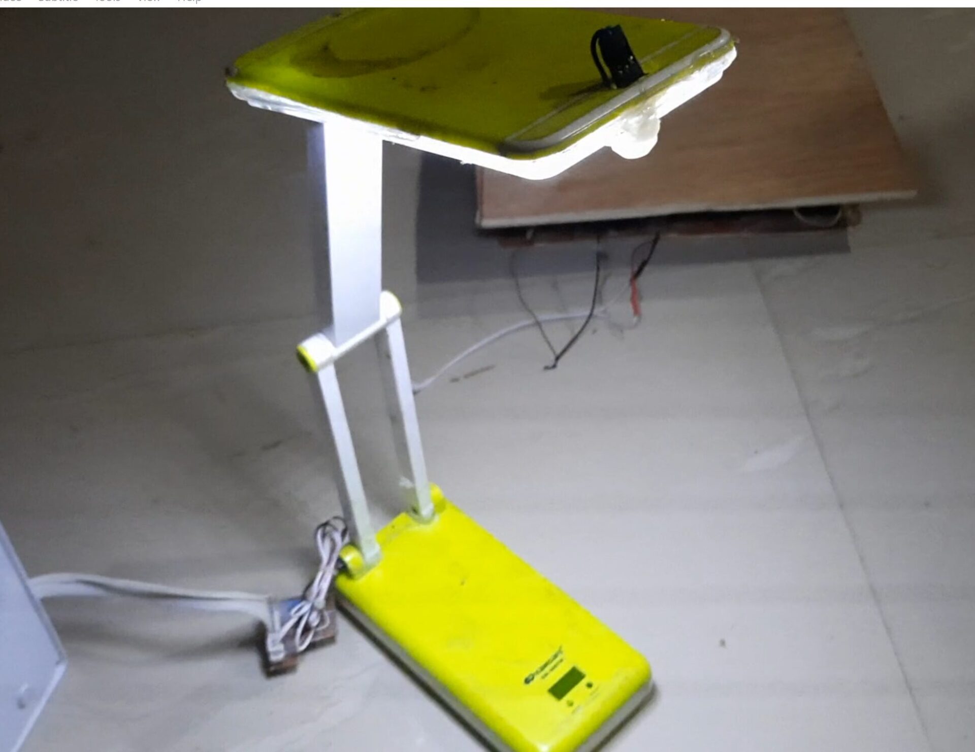
- We tested the entire system to ensure all components work seamlessly.
- We also checked if the LEDs respond to motion and light levels correctly.
- And also verified the PZT transducers recharge the batteries efficiently.
Why Choose a Smart Street Light System?

Traditional street lights consume massive amounts of electricity, leading to higher costs and energy wastage. A smart street light system solves these issues by:
- Automatically adjusting illumination based on motion.
- Utilizing renewable energy sources like footstep power.
- Providing a cost-effective and sustainable solution for public lighting.
In addition, this project is a great way to reuse components like LED arrays and batteries, reducing e-waste and promoting recycling.
Applications of the Smart Street Light
The smart street light system can be implemented in various areas, including:
- Urban Streets and Highways: Reduces energy consumption in busy city areas.
- Parks and Pathways: Provides sufficient lighting for safety while saving power.
- Remote Areas: Ideal for locations without access to the power grid.
- Campuses and Residential Areas: Ensures security while maintaining energy efficiency.
- Parking Lots: Detects vehicle or human motion to light up specific areas.
Challenges and Future Improvements
While the current project works effectively, here are some challenges and improvements to consider:
Challenges:
- PZT Efficiency: Footstep energy generation is still limited in terms of output.
- Battery Capacity: Higher capacity batteries may be needed for larger-scale systems.
Future Improvements:
- Integrate solar panels to supplement the charging system.
- Use a more efficient motion sensor to detect smaller movements.
- Implement IoT connectivity to monitor and control the street light remotely.
Conclusion
The Smart Street Light System Project is a shining example of how technology and sustainability can work hand-in-hand. By combining motion detection, energy-efficient lighting, and footstep power generation, this design offers a cost-effective and eco-friendly solution to traditional street lighting.
Whether you’re an engineering student, a DIY enthusiast, or someone passionate about renewable energy, this project is a great step toward building smarter and greener cities.
FAQs
1. How does the smart street light save energy?
The smart street light saves energy by dimming during inactivity and only increasing brightness when motion is detected using a PIR sensor.
2. What role does the PZT transducer play in this project?
The PZT transducer converts footstep pressure into electrical energy, which recharges the batteries used to power the street light.
3. Can this system work without an Arduino Mega?
While the Arduino Mega is ideal for this project, other microcontrollers like Arduino Uno can be used with minor adjustments.
