Blog

  • GPS and SMS Based Fall Detection and Prevention Project

    GPS and SMS Based Fall Detection and Prevention Project

    This tutorial is about design and construction of a GPS and SMS based fall detection and prevention project for the elderly. The project uses at knowing when an elderly person has fallen and would inform the doctor or physician of his or her exact location by effectively detecting the fall, by placing a call and sending an SMS to them. It also tells the physician or doctor if an elderly is prone to have a fall. We will be going through how it is done step by step, so stick around and ensure you read until the end.
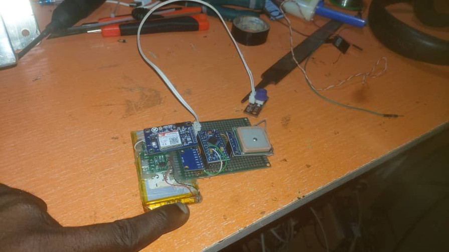
    Fall Detection and Prevention

    Components Required

    The following materials can be gotten from our online shop here or any online store

    • Gyroscope
    • Arduino Pro-mini baord
    • GPS Module
    • GSM Module
    • Li-ion 3.3V 5500mAh Battery
    • LiPO charging Module

    With the above mentioned components, we can proceed to understanding the schematic diagram.

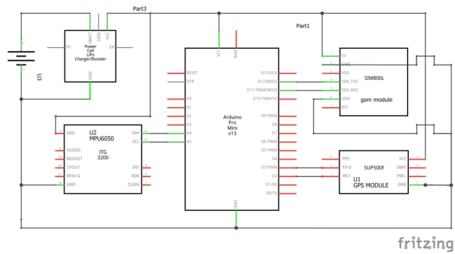
    The Schematic Diagram
    Fall detection and prevention

    Explanation to The Schematic Diagram

    The schematic diagram of the fall detection and prevention project above shows that the GSM module is connected Arduino Pro-mini board using serial communication and the GPS module is also connected to the board. The gyroscope MPU6060 is connected using I2C protocol and the LiPo battery charger module powers the whole system.
    Fall detection and prevention

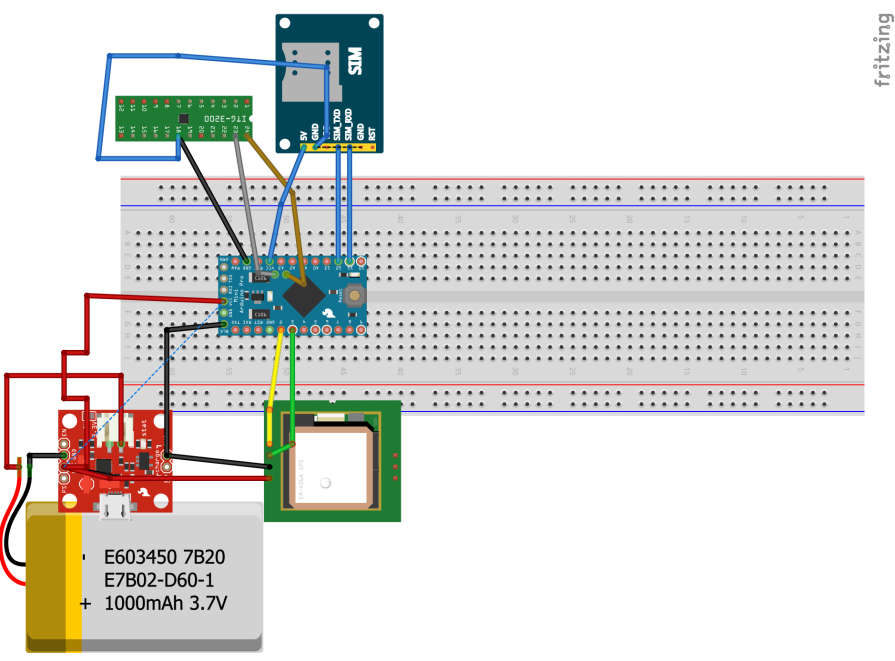
    The breadboard view of the fall detection and prevention project is shown above. This could be better understood since it is the pictorial form of it.

    The Arduino Sketch

    #define TINY_GSM_MODEM_SIM800
    // Increase RX buffer if needed
    //#define TINY_GSM_RX_BUFFER 512
    #include <TinyGPS++.h>
    #include <TinyGsmClient.h>
    #include <ArduinoHttpClient.h>
    #include <GSMSimCall.h>
     #include <Wire.h>
    // The TinyGPS++ object
    TinyGPSPlus gps;// Uncomment this if you want to see all AT commands
    //#define DUMP_AT_COMMANDS
    
    // Set serial for debug console (to the Serial Monitor, default speed 115200)
    #define SerialMon Serial
    #define RESET_PIN 13
    // Use Hardware Serial on Mega, Leonardo, Micro
    //#define SerialAT Serial1
    
    // or Software Serial on Uno, Nano
    #include <SoftwareSerial.h>
    SoftwareSerial SerialAT(11, 12); // RX, TX
    GSMSimCall call(SerialAT, RESET_PIN);
    // The serial connection to the GPS device
    SoftwareSerial ss(2, 3);
    
    // Your GPRS credentials
    // Leave empty, if missing user or pass
    const char apn[]  = "internet";
    const char user[] = "";
    const char pass[] = "";
    
    // Server details
    String ress = "/trigger/Fall/with/key/bBoafo8uqrZq72TzdrU0ye?&value1=";
    const char server[] = "maker.ifttt.com";
    char* resource; 
    const int  port = 80;
    
    String Location = "";
    const char number1[] = {"0**********"};
    const char number2[] = {"0**********"};
    String link = "click here to locate Mr. ANC: https://www.google.com/maps/place/";
    int length = 11;
    String caller;
    const int MPU_addr = 0x68; // I2C address of the MPU-6050
     int16_t AcX, AcY, AcZ, Tmp, GyX, GyY, GyZ;
     float ax = 0, ay = 0, az = 0, gx = 0, gy = 0, gz = 0;
     boolean fall = false; //stores if a fall has occurred
     boolean trigger1 = false; //stores if first trigger (lower threshold) has occurred
     boolean trigger2 = false; //stores if second trigger (upper threshold) has occurred
     boolean trigger3 = false; //stores if third trigger (orientation change) has occurred
     byte trigger1count = 0; //stores the counts past since trigger 1 was set true
     byte trigger2count = 0; //stores the counts past since trigger 2 was set true
     byte trigger3count = 0; //stores the counts past since trigger 3 was set true
     int angleChange = 0;
    
    #ifdef DUMP_AT_COMMANDS
      #include <StreamDebugger.h>
      StreamDebugger debugger(SerialAT, SerialMon);
      TinyGsm modem(debugger);
    #else
      TinyGsm modem(SerialAT);
    #endif
    
    TinyGsmClient client(modem);
    HttpClient http(client, server, port);
    
    void setup() {
      // Set console baud rate
      SerialMon.begin(9600);
      delay(10);
      ss.begin(9600);
      // Set GSM module baud rate
      SerialAT.begin(9600);
      delay(500);
    
      // Restart takes quite some time
      // To skip it, call init() instead of restart()
      SerialMon.println(F("Initializing modem..."));
      modem.restart();
    
      String modemInfo = modem.getModemInfo();
      SerialMon.print(F("Modem: "));
      SerialMon.println(modemInfo);
      SerialMon.print(F("Waiting for network..."));
      if (!modem.waitForNetwork()) {
        SerialMon.println(" fail");
        delay(10000);
        return;
      }
      SerialMon.println(" OK"); 
      Wire.beginTransmission(MPU_addr);
       Wire.write(0x6B);  // PWR_MGMT_1 register
       Wire.write(0);     // set to zero (wakes up the MPU-6050)
       Wire.endTransmission(true);
    }
    
    void loop() {
      Serial.println("LOOP");
    //  update_Location();  
      Serial.println(Location);
      
        sendEmail();
      //sendSMS();
      //sendEmail();
      //sendSMS(caller, link+Location);
      delay(5000);
    } 


    This source code can still be downloaded from the Github page free. Just downlaod and unzip it if it appears in a .zip file.

    Fall Detection: The Soldering and Construction
    construction of fall detection project

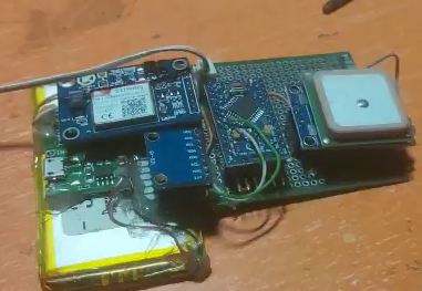
    The construction of the project was done as shown above. It began with soldering of the parts involved together using the veroboard and using female headerpins to connect them. The LiPo charging module was placed in an orientation where there can be an opening for charging the battery. Whereas the gyroscope was made to be sensitive of change in orientations and axial movements.

    Casing and Making the Project Wearable
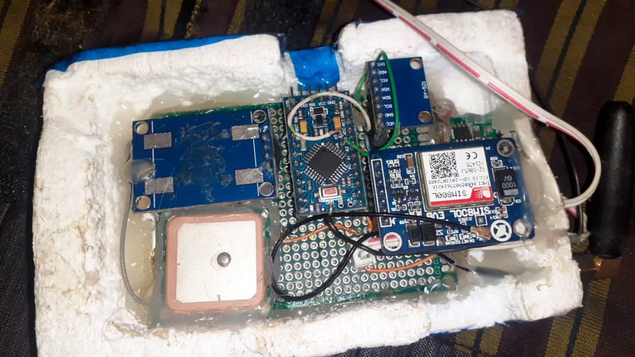
    fall detection project

    The whole project is placed inside white form and then it was glued with the parts as shown above. The enclosure is made to slide in and easily slide out.
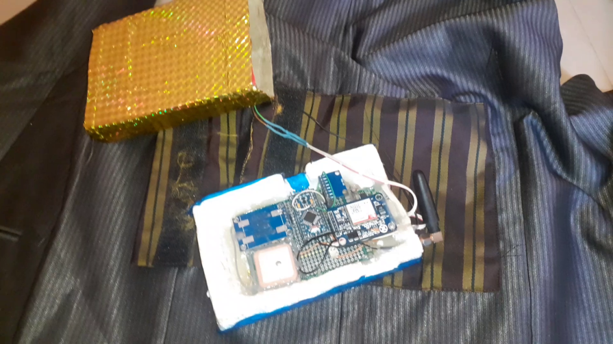
    fall detection project

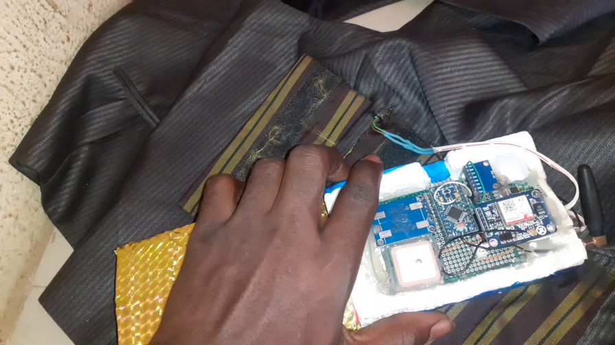
    The whole thing was sown onto a jacket, the jacket came with a pouch that could house the fall detection project. Thereby making it wearable.
    Conclusion

    The fall detection and prevention project was designed for the elderly. It helps their caretakers and physician track their whereabout and also it notifies them if they have had any fall incidents. We have demonstrated how to achieve this and have included all the necessary tools needed. Let us know in the comment section if you were able to recreate this project on your own.

  • My Killer  Vacation Romantic Novel Review

    My Killer Vacation Romantic Novel Review

    My Killer  Vacation

    Overview

    In My Killer Vacation romantic novel review. Taylor and her loving brother were supposed to be on a quiet vacation in the lovely, sunny Cape Cod, but finding a body in their rental home has seriously interfered with their plans to tan. Taylor has spent many hours listening to true crime podcasts, but the harsh, crude bounty hunter who is here to apprehend the murderer doesn’t think she can be of any assistance. Not to mention her rewarding profession as a teacher managing second graders.

    The murder-solving duo no one wanted is made up of a brazen bounty hunter and a vivacious elementary school teacher, but because of these annoying attempts on Taylor’s life, they must work together come hell or high water.

    Myles isn’t watching over an amateur detective; he’s just there to perform his job. However, having Taylor around is becoming less and less of a burden. She can be distracted, headstrong, and unable to avoid danger. She also inspires him to think of the house he left behind three years ago because she is strong and lovely. In other words, he risks losing his peace of mind due to the insatiable appetite and protectiveness she is awakening. Myles needs to solve this crime and get back on the road before he falls any more into this perilous fascination. Will she be taken from him by fate before Myles realizes she has been on his path the entire time?

    Product Details


    ISBN-13: 9780063329997
    Publisher: HarperCollins Publishers
    Publication date: 01/31/2023
    Sold by: HARPERCOLLINS
    Format: eBook
    Pages: 320
    Sales rank: 369
    File size: 2 MB

    About the Author

    My Killer  Vacation

    #1 New York Times bestselling author Tessa Bailey can solve all problems except for her own, so she focuses those efforts on stubborn, fictional blue-collar men and loyal, lovable heroines. She lives on Long Island avoiding the sun and social interactions, then wonders why no one has called. Dubbed the “Michelangelo of dirty talk,” by Entertainment Weekly, Tessa writes with spice, spirit, swoon and a guaranteed happily ever after. Catch her on TikTok at @authortessabailey or check out tessabailey.com for a complete list of books.

    Get the full details of this post in the link below:

    Barnes and nobles

    Read More

  • Saving Kyla Romantic Novel Review

    Saving Kyla Romantic Novel Review

    Saving Kyla

    Overview

    In the romantic novel Saving Kyla , international assassin Kyla Russell is carrying out her final mission in Afghanistan while posing as a journalist. When she learns that her task is to murder a man who doesn’t deserve it, she recoils. Although Kyla wants to leave the company, her handler would rather to see her killed than let her escape. Her only chance of escaping her Taliban captivity with a group of mercenaries is to allow herself to be drawn into a daring rescue by a hot former Navy SEAL. The mercenaries are flown back to the United States with Kyla, who is given a new home in Yellowstone.

    At his father’s resort in West Yellowstone, Stone establishes a Yellowstone division of the Brotherhood Protectors with his group of ex-SEALs turned mercenaries. Stone, who is struggling with his attraction to the brave journalist, doesn’t fully appreciate Kyla’s combat experience or his developing feelings for her when he recruits her as the team’s communications expert. The group rallies around her when her past makes an appearance. Stone and Kyla face the enemy together in an effort to silence an assassin while also giving way to their desire to one another.

    Product Details


    BN ID: 2940161000106
    Publisher: Twisted Page Inc
    Publication date: 02/22/2022
    Series: Brotherhood Protectors Yellowstone , #1
    Sold by: Barnes & Noble
    Format: eBook
    Sales rank: 448
    File size: 764 KB

    Saving Kyla

    About the Author

    New York Times and USA Today Bestselling author, Elle James lived on a small ranch in Texas for twenty years, raising ostrich, emus, rheas, cattle, horses and goats. She served in the U.S. Army and Air Force Reserves and now lives in beautiful Arkansas. She writes romantic suspense with military heroes, cowboys and strong female characters. She enjoys four-wheeling, traveling, adventure and her yorkies, Bandit and Charli! Her booklist can be found at www.ellejames.com

    Get the full details of this post in the link below:

    Barnes and nobles

    Read More

  • Protecting Remi ‘romantic PDF Review’

    Protecting Remi ‘romantic PDF Review’

    Protecting Remi

    In Protecting Remi book. Remi Stephenson didn’t anticipate the day’s events, which included meeting a handsome, strong, courageous Navy SEAL after their privately hired boat’s captain purposefully left them both stranded in the middle of the ocean. The SEAL and the voluptuous, nerdy artist had an undeniable connection, even though she hadn’t expected to get more than a second glance from him. They were organizing a reunion when they got back to Southern California even before they were saved.

    Wolf Steel was Vincent “Kevlar” Hill’s friend and mentor, and he had always coveted what he had. a devoted life partner to share it with. But the obstacle he faced as a Navy SEAL appeared insurmountable. Up until he ended up in the middle of the ocean with the most fascinating, seductive woman he had ever encountered.

    In order to find out who hated either him or Remi enough to try to get rid of them and to prevent their hidden enemy from succeeding in ending not only their budding relationship but also their lives, Kevlar must rely on the knowledge of his teammates, a former SEAL named Tex, and all of Wolf’s connections.

    Product Details


    BN ID: 2940160983998
    Publisher: Stoker Aces Production LLC
    Publication date: 07/02/2024
    Series: SEAL of Protection: Alliance
    Sold by: Barnes & Noble
    Format: eBook
    Sales rank: 204

    About the Author

    Protecting Remi

    New York Times, USA Today, #1 Amazon Bestseller, and #1 Wall Street Journal Bestselling Author, Susan Stoker has spent the last twenty-three years living in Missouri, California, Colorado, Indiana, Texas, and Tennessee and is currently living in the wilds of Maine. She’s married to a retired Army man (and current firefighter/EMT) who now gets to follow her around the country.

    Get the full details of this in the link below:

    Barnes and nobles

    Read More

  • Missing Evidence PDF Review

    Missing Evidence PDF Review

    Missing Evidence PDF Review. He possesses a unique skill set to unleash the truth.
    She’s a veteran under protection.
    When danger deepens, this unlikely duo sets out to wreak havoc on the man who murdered her brother.

    When Garrett Crown’s friend is murdered on his watch, he’s devastated. Running from his demons, he leaves the city and returns to his family homestead in Kentucky, hopeful that small-town life and tranquility will once again be his companion.

    Riley Murphy, aka Skeeter, spent ten years in the Army only to be ousted when she claimed that her commanding officer had beat her, and left her for dead. Soon after, her career Army brother commits suicide. Skeeter finds evidence of foul play, but her accusations fall on deaf ears when she names her commanding officer.

    Fearing for her life, she takes refuge at the Crown Ranch under the protection of two of her brother’s former military friends, one being Garrett’s brother.

    When reminders related to her past with her commanding officer show up at her doorstep, she again fears death.

    Garrett feels a powerful attraction to Skeeter and vows to protect her, no matter the cost. He failed his friend, but he will NOT fail Skeeter.

    Product Details


    BN ID: 2940161037836
    Publisher: Valerie J. Clarizio
    Publication date: 05/18/2023
    Series: Crown Ranch
    Sold by: Barnes & Noble
    Format: eBook
    Sales rank: 85
    File size: 351 KB

    About the Author


    Valerie Clarizio is a USA Today bestselling author who lives in romantic Door County Wisconsin with her husband. She loves to read, write, and spend time at her cabin in the Upper Peninsula of Michigan.

    She’s lived her life surrounded by men, three brothers, a husband, and a male Siamese cat who required his own instruction manual. Keeping up with all the men in her life has turned her into an outdoors enthusiast, of which her favorite activity is hiking in national parks. While out on the trails, she has plenty of time to conjure up irresistible characters and unique storylines for her next romantic suspense, time travel, or contemporary romance novel.

    Get the full details of this post in the line below:

    Barnes and nobles

    Read More

  • Temperature Control Fan Arduino Proteus Simulation

    Temperature Control Fan Arduino Proteus Simulation

    In this post today, we will be doing a temperature control fan simulation using Arduino and Proteus Design and Circuit IDE. This post is a continuation of of our previous Home Automation Simulation. In the previous post, we were able to turn on and off the light bulb using the PIR motion sensor. In this very post, we will be adding a digital and humidity sensor (DHT11) to sensor the virtual temperature of the room and hence regulate the temperature by ensuring that when the temperature goes too hot, the fan increases its speed to the maximum and when the temperature is too cold, the fan’s speed decreases until it finally turns off.

    Temperature control fan simulation

    Temperature Fan Control Simulation

    To proceed further on this, we are assuming that you have the knowledge of how to install the Proteus version used in this tutorial by reading the previous post and also how to create a new project on Proteus Design and Circuit IDE. It is pretty much easy, just follow the previous blog post.

    The Components Needed

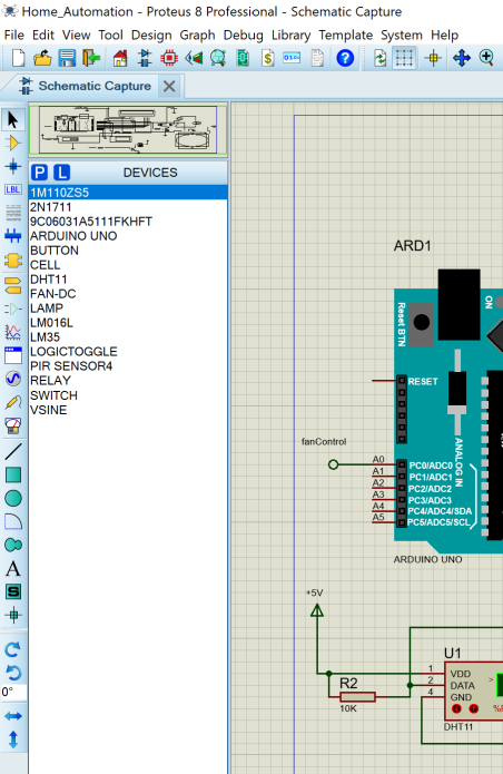
    The Proteus components needed for this tutorial is listed in the image above. You can just type the exact part number or model names as show there. However in summary we used the Zener diode 1M110Z5S as flywheel for the relay module created with the NPN transistor. The Arduino Uno is the heart and brain of the simulation. We used a push-button and a switch to to give the user control over the fan and the simulated room light bulb. This means that if the user wanted the fan to be turned on and regulated by the internal temperature sensor (DHT11), he/she could just press the switch. But the light bulb is triggered by the motion sensor automatically. However if the user wanted the light bulb to remain turned off, he/she could just push the push-button.

    Temperature fan control

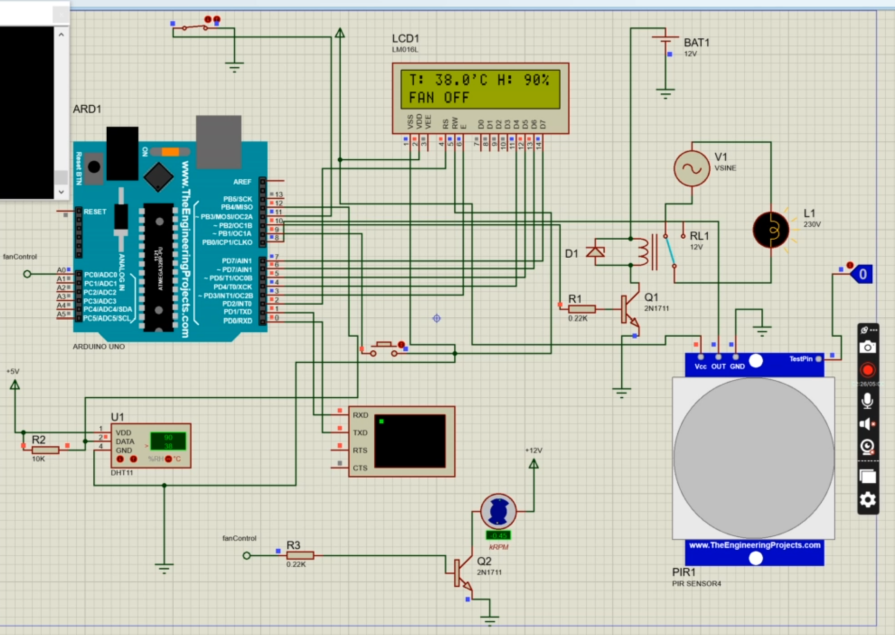
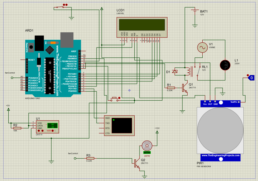
    The connection to the whole components is shown in the above diagram, we just need to add a few components to our last tutorial. We needed the DHT11 sensor and this can be gotten from the search menu after we click on pick component icon. The DC fan too and the extra NPN transistor that was connected to it. We used a 12V power supply to power it.

    Programming the Proteus Simulation

    The Arduino Sketch

    The Arduino sketch to this design is found in the simulation folder on Github. You can download the file and unzip, and open it in your Arduino IDE. Alternatively, you can also just copy the code off here.

    // include the library code:
    #include <LiquidCrystal.h>
    #include "DHT.h"
    
    //show where the actuator and sensors are connected
    #define pirPin 8
    #define pushButtonPin 9
    #define relayPin 10
    int fanSwitch = 11;
    int fanControl = A0;
    //show where the dht11 sensor was connected
    #define DHTPIN 12
    
    #define DHTTYPE DHT11  // we are using DHT11
    
    DHT dht(DHTPIN, DHTTYPE);
    
    // Variables will change:
    int ledState = HIGH;        // the current state of the output pin
    int buttonState;            // the current reading from the input pin
    int lastButtonState = LOW;  // the previous reading from the input pin
    
    unsigned long lastDebounceTime = 0;  // the last time the output pin was toggled
    unsigned long debounceDelay = 10;    // the debounce time; increase if the output flickers
    
    // state where the arduino pin number it is connected to on LCD
    const int rs = 2, en = 3, d4 = 4, d5 = 5, d6 = 6, d7 = 7;
    LiquidCrystal lcd(rs, en, d4, d5, d6, d7);
    
    void setup() {
      // set up the LCD's number of columns and rows:
      lcd.begin(16, 2);
      //begin the serial monitor comm.
      Serial.begin(9600);
      //beging the dht11 sensor
      dht.begin();
      //state the fxn for the inputs and outputs
      pinMode(pirPin, INPUT);
      pinMode(pushButtonPin, INPUT_PULLUP);
      pinMode(relayPin, OUTPUT);
      pinMode(fanSwitch, INPUT_PULLUP);
      pinMode(fanControl, OUTPUT);
      // Print a welcome message to the LCD.
      lcd.setCursor(0, 0);
      lcd.print("HELLO THERE?");
      delay(100);
      lcd.clear();
      lcd.setCursor(0, 0);
      lcd.print("MOTION BASED");
      lcd.setCursor(0, 0);
      lcd.print("HOME AUTOMATION");
      delay(100);
      lcd.clear();
      lcd.setCursor(0, 0);
      lcd.print("SIMULATION");
      delay(100);
      lcd.clear();
      //read the pir sensor
      while (digitalRead(pirPin) == 0) {
        lcd.clear();
        lcd.setCursor(0, 0);
        lcd.print("   NO MOTION");
        lcd.setCursor(0, 1);
        lcd.print("DETECTED IN ROOM");
        Serial.println("NO MOTION DETECTED");
        delay(50);
        turnOffBulb();
        delay(100);
      }
      if (digitalRead(pirPin) == 1) {
        lcd.clear();
        lcd.setCursor(0, 0);
        lcd.print("MOTION DETECTED");
        Serial.println("MOTION DETECTED");
        delay(50);
        turnOnBulb();
        delay(100);
      }
    }
    
    void turnOnBulb() {
      digitalWrite(relayPin, HIGH);
      Serial.println("LIGHT BULB TURNED ON");
      lcd.clear();
      lcd.setCursor(0, 0);
      lcd.print("LIGHT BULB");
      lcd.setCursor(0, 1);
      lcd.print("TURNED ON");
    }
    
    void turnOffBulb() {
      digitalWrite(relayPin, LOW);
      Serial.println("LIGHT BULB TURNED OFF");
      lcd.clear();
      lcd.setCursor(0, 0);
      lcd.print("LIGHT BULB");
      lcd.setCursor(0, 1);
      lcd.print("TURNED OFF");
    }
    
    void controlFan() {
    
      float h = dht.readHumidity();
      // Read temperature as Celsius (the default)
      float t = dht.readTemperature();
      // Read temperature as Fahrenheit (isFahrenheit = true)
      float f = dht.readTemperature(true);
    
      //print out the readings
      Serial.print(F("Humidity: "));
      Serial.print(h);
      Serial.print(F("%  Temperature: "));
      Serial.print(t);
      Serial.print(F("°C "));
      Serial.println(digitalRead(fanSwitch));
    
      lcd.clear();
      lcd.setCursor(0, 0);
      lcd.print("T: " +String(t, 1)+ "'C H: " + String(h,0) + "%");    
    
      if (digitalRead(fanSwitch)== 1) {
        if (t > 37.00) {
          for (int i = 50; i < 256; i++) {
            analogWrite(fanControl, i);
            lcd.setCursor(0, 1);
            lcd.print("FAN ON"); 
          }
        }
          if (t < 35.00) {
            analogWrite(fanControl, LOW);
            lcd.setCursor(0, 1);
            lcd.print("FAN OFF"); 
          }    
      }
    
      if (digitalRead(fanSwitch) == 0) {
        analogWrite(fanControl, LOW);
        lcd.setCursor(0, 1);
        lcd.print("FAN OFF"); 
      }
    }
    
    void loop() {
      //read the pir sensor
      bool readPir = digitalRead(pirPin);
      // read the state of the switch into a local variable:
      int reading = digitalRead(pushButtonPin);
      controlFan();
      delay(100);
      // If the switch changed, due to noise or pressing:
      if (reading != lastButtonState) {
        // reset the debouncing timer
        lastDebounceTime = millis();
      }
    
      if ((millis() - lastDebounceTime) > debounceDelay) {
        // if the button state has changed:
        if (reading != buttonState) {
          buttonState = reading;
    
          // only toggle the LED if the new button state is HIGH
          if (buttonState == HIGH) {
            ledState = !ledState;
          }
        }
      }
    
      //use an if condition to check for the motion
      if (ledState == 0) {
        if (readPir == 1) {
          lcd.clear();
          lcd.setCursor(0, 0);
          lcd.print("MOTION DETECTED");
          Serial.println("MOTION DETECTED pushbutton: " + String(reading) + " LED state: " + String(ledState));
          delay(50);
          turnOnBulb();
          delay(100);
        }
      }
    
      if (ledState == 1) {
        if (readPir == 1) {
          lcd.clear();
          lcd.setCursor(0, 0);
          lcd.print("MOTION DETECTED");
          lcd.setCursor(0, 1);
          lcd.print("USER OFF LIGHT");
          Serial.println("MOTION DETECTED pushbutton: " + String(reading) + " LED state: " + String(ledState));
          delay(50);
          turnOffBulb();
          delay(100);
        }
    
        if (readPir == 0) {
          lcd.clear();
          lcd.setCursor(0, 0);
          lcd.print("NO MOTION DETTED");
          lcd.setCursor(0, 1);
          lcd.print("USER OFF LIGHT");
          Serial.println("NO MOTION DETECTED pushbutton: " + String(reading) + " LED state: " + String(ledState));
          delay(50);
          turnOffBulb();
          delay(100);
        }
      }
      // save the reading. Next time through the loop, it'll be the lastButtonState:
      lastButtonState = reading;
      delay(100);
    }


    Explanation of The Arduino Code

    Temperature control fan simulation: Arduino code

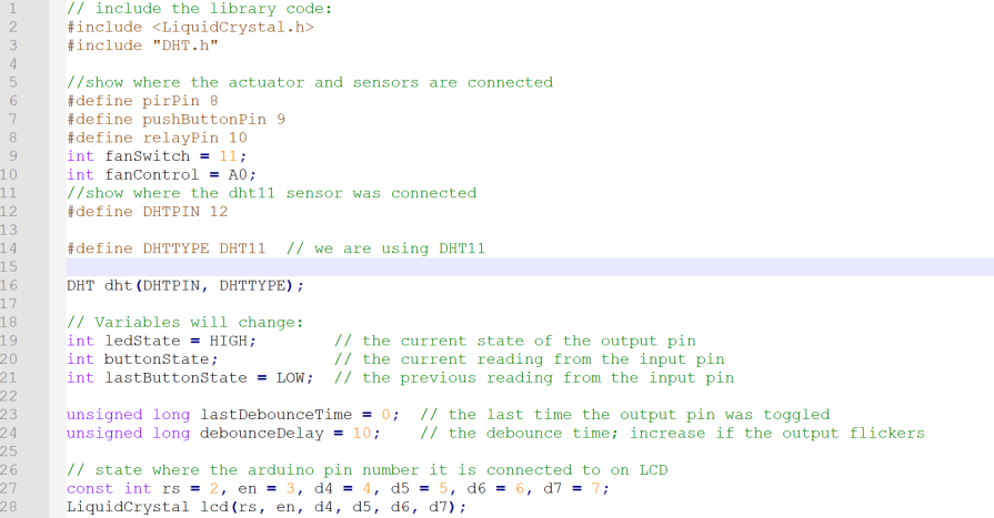
    We began by including the LCD library. This is needed to show the user what is going on in the simulated virtual room. We also included the library for the temperature sensor, DHT11 in code line 3. We declared and defined where we connected the PIR sensor digital output pin (which is digital pin 8). The relay transistor base is connected to digital pin 10 on the Uno board, the Fan Auto Mode switch is connected to D11, while the DHT11 digital output pin is connected to D12 on the virtual Arduino Uno board. This as shown from code line 6 through 12.

    We used dome variables to hold the states of the AC light bulb so as to allow the user change the turning on and off of the bulb. These variables in code line 19 and 21 helps us to enable the user to turn off the light bulb when the motion sensor triggers it on and it stays off. And turns back on when the user presses it and for it to sense motion and come on. The code line 28 is where we connected the LCD digital pins onto the Arduino Uno board pins.

    Arduino Hex Code

    Arduino HEX code

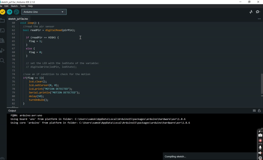
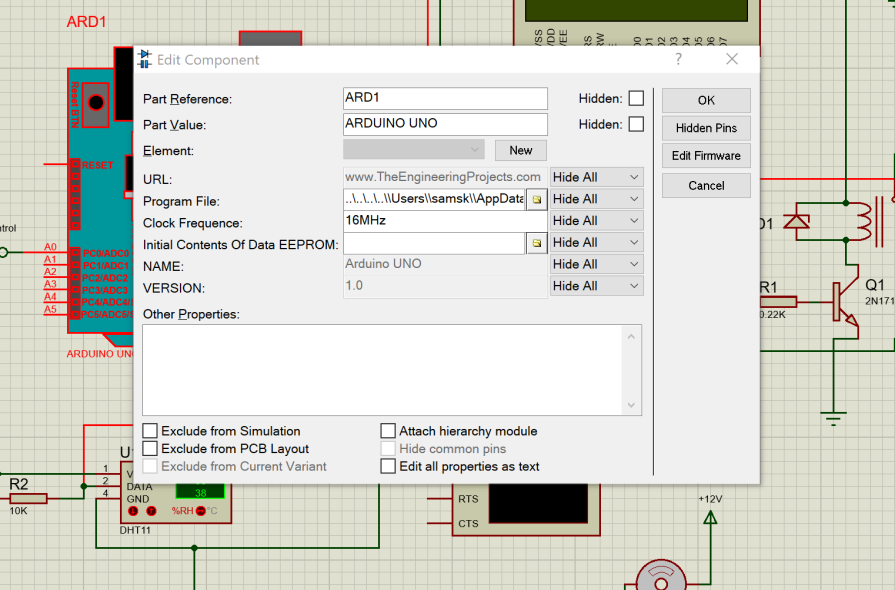
    The HEX code is located at the Arduino IDE output console, as stated in the previous post, just copy this address to the HEX code. And paste it into the Arduino Uno by doubleclicking on the components and pasting it into the ‘program file’ input.

    Pasting Arduino HEX code into the Arduino Uno Proteus IDE

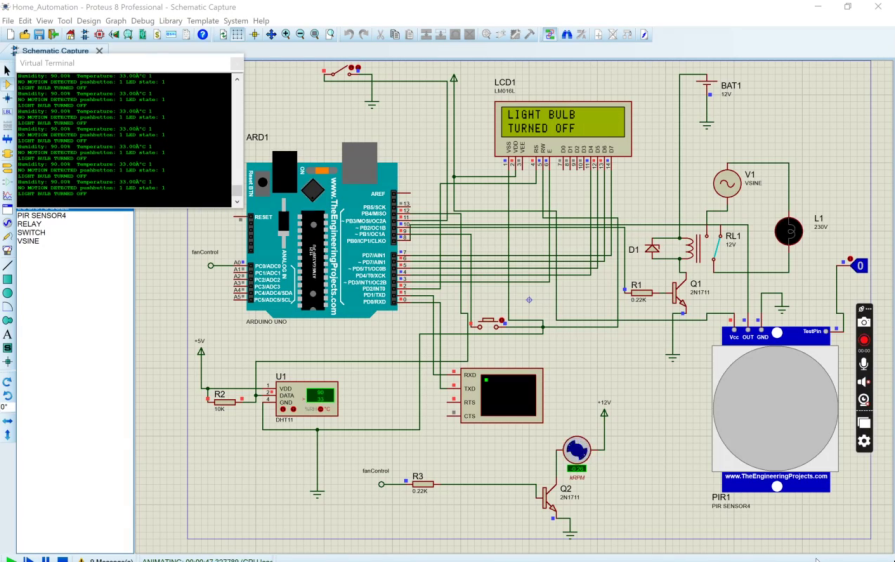
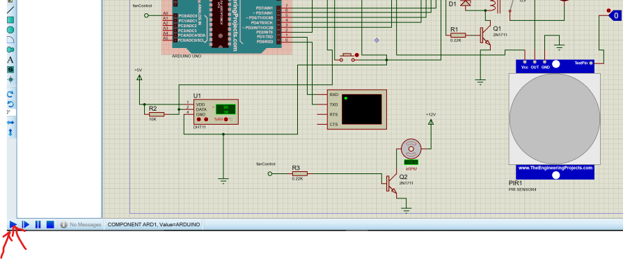
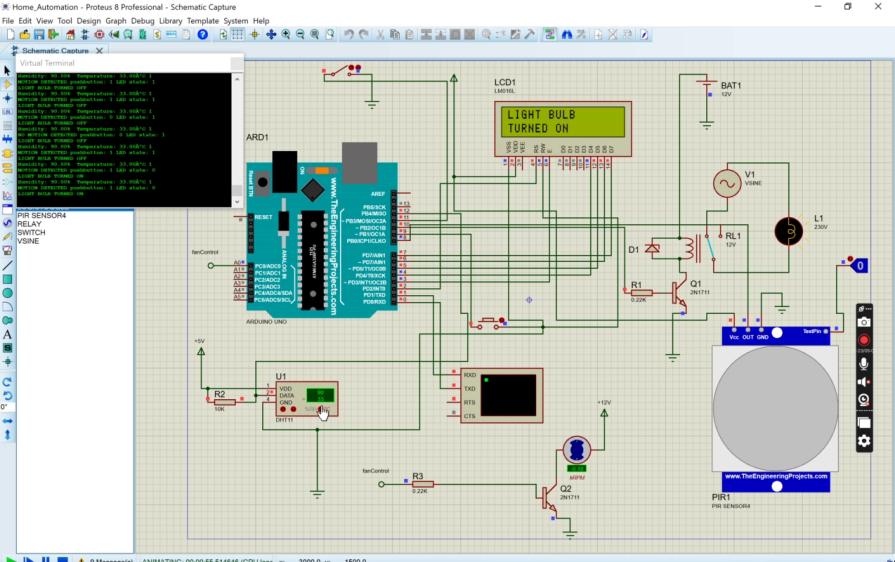
    Once this is done, we can proceed to the next step which is actually running the simulation by moving down to the lower panel and click on the play button. This would take just about 1-2 seconds. And the temperature control fan simulation should start running if you got everything connected properly and both the HEX file addresses for the PIR sensor and Arduino Uno set properly.

    running Proteus simulation

    As show below, the simulation would show the temperature of the virtual room and the humidity in degree Celsius and percentage respectively. It will also show the current state of the fan. It is either turned on or off.

    Arduino fan simulation

    To simulate the temperature changes, we go to the DHT11 sensor component while the simulation is still running. Please note that the simulation may not be running in real time. This is not really a problem since we can still simulate what we intended to do.

    changing the temperature of DHT11

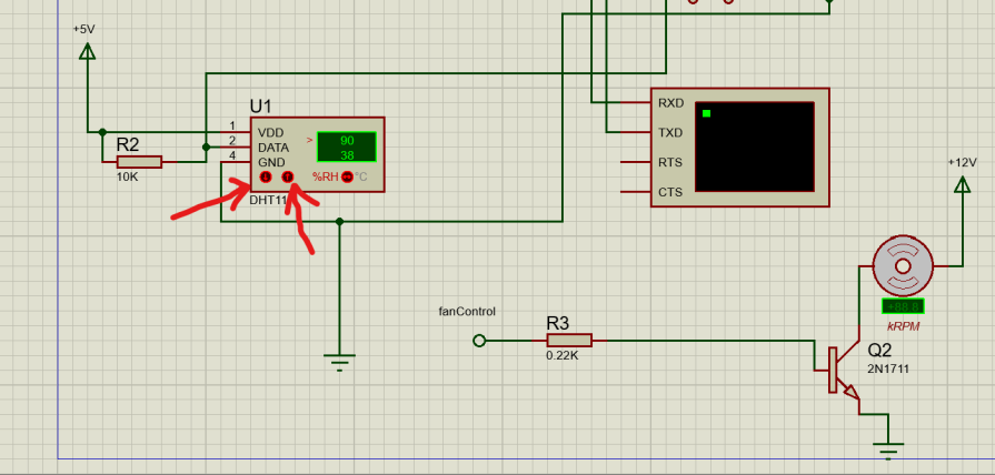
    Clicking on any of the two buttons as highlighted out above would change the printed temperature sensed by the DHT11 sensor. The up arrow button increases the temperature whereas the down button decreases the temperature.

    simulation

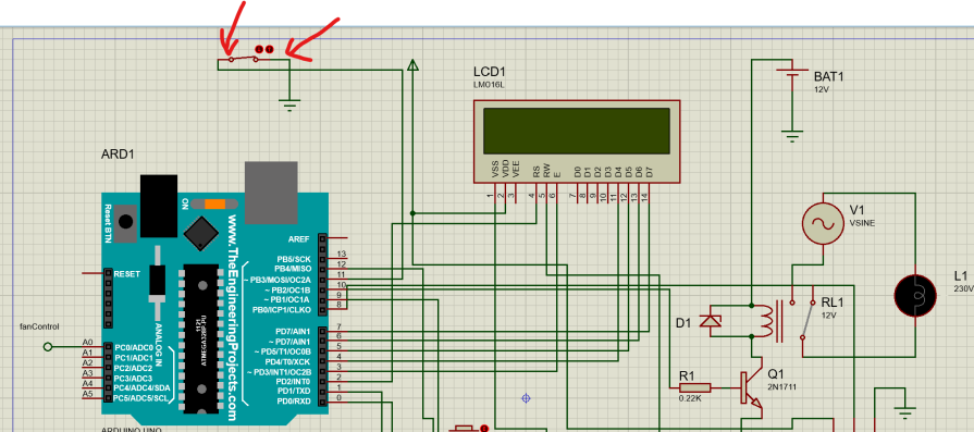
    However, if the switch shown above is not turned on (pressed down), the fan won’t start spinning. But if it is as, as shown above, then we can expect the DC fan to rotate. Also, the speed of the fan is controlled by the temperature of the DHT11 sensor. According to the program written, when the temperature is above 37 degree Celsius, the Fan automatically go into activation and would be running at a speed controlled by PWM signal feed into the base of the NPN transistor. And if the temperature is below 35 degrees Celsius, the Fan would automatically stop. These set temperatures are the human body temperatures that are medically know to cause cold and hot.

    Conclusion

    temperature and motion control home automation

    We have so far, in this temperature control fan simulation post, designed and simulated a home automation system that uses the PIR motion sensor to turn on the virtual room light and also used a digital and humidity sensor DHT11 to control the speed of the fan running in the virtual room. All the components and simulation is running smoothly. Let us know if you remade this on your own or if you added any modifications in the comment section. You can also watch the YouTube video to see the demonstration.

    Read More

  • A Group of Legged Robots Explores Planet-like Analog Landscapes.

    A Group of Legged Robots Explores Planet-like Analog Landscapes.

    Such adorable legged robots explores…Humanity may one day mine and exploit the raw resources found on the moon. Missions to better investigate Earth’s satellite and locate minerals are already being planned by a number of space agencies, including the European Space Agency (ESA). This necessitates the use of suitable exploration vehicles. The idea of sending a full team of vehicles and flying apparatuses that work in harmony on an exploratory mission is now being pursued by Swiss researchers led by ETH Zurich.

    Three ANYmal, a class of legged robot created at ETH, were given a variety of measuring and analytical tools by the researchers, which could make them acceptable exploration tools in the future. They tested these robots in Switzerland and at the European Space Resources Innovation Center (ESRIC) in Luxembourg, where the Swiss team and German teammates previously won a European competition for lunar exploration robots. Finding and identifying minerals on a test site that was made to resemble the surface of the moon was required for the competition. Scientists reveal how they use a team of robots to explore an uncharted landscape in the most recent issue of the journal Science Robotics.

    Insurance against failure

    “Using multiple robots has two advantages,” explains Philip Arm, a doctoral student in the group led by ETH Professor Marco Hutter. “The individual robots can take on specialized tasks and perform them simultaneously. Moreover, thanks to its redundancy, a robot team is able to compensate for a teammate’s failure.” Redundancy in this case means that important measuring equipment is installed on several robots. In other words, redundancy and specialization are opposing goals. “Getting the benefits of both is a matter of finding the right balance,” Arm says.

    The researchers at ETH Zurich and the Universities of Basel, Bern and Zurich solved this problem by equipping two of the legged robots as specialists. One robot was programmed to be particularly good at mapping the terrain and classifying the geology. It used a laser scanner and several cameras—some of them capable of spectral analysis—to gather initial clues about the mineral composition of the rock. The other specialist robot was taught to precisely identify rocks using a Raman spectrometer and a microscopy camera.

    The third robot was a generalist: it was able to both map the terrain and identify rocks, which meant that it had a broader range of tasks than the specialists. However, its equipment meant that it could perform these tasks with less precision. “This makes it possible to complete the mission should any one of the robots malfunction,” Arm says.

    Get the full details of the post in the link below:

    Techexplro

    Read More

  • Increasing the Stability of Perovskite Solar Cells at High Temperatures

    Increasing the Stability of Perovskite Solar Cells at High Temperatures

    solar panels array

    solar cells at high temperatures. High power-conversion efficiency and inexpensive solution processing have made perovskite solar cells (PSCs) popular. However, assuring their stability at high temperatures has been difficult because the “interfaces”—the points of contact between their many layers—are prone to degradation, which reduces performance and causes energy loss.

    In a new study, researchers have found that they can minimize PSC degradation at high temperatures by using fluorinated aniliniums, a class of compounds used in pharmaceuticals, agrochemicals, and materials science. The study was led by Michael Grätzel at EPFL, Edward Sargent at the University of Toronto, and Kenneth Graham at the University of Kentucky. It is published in Science.

    The researchers incorporated fluorinated aniliniums in the “interfacial passivation” step of PSC fabrication. Interfacial passivation is a technique used to enhance the stability and performance of interfaces between different layers or materials to minimize defects, reduce charge recombination, and improve overall efficiency and stability.

    Adding fluorinated aniliniums enhanced the stability of PSCs by avoiding progressive ligand intercalation. This prevented the continuous penetration of ligand molecules between the layers or structures of the perovskite material, which destroys the integrity of the crystals, leading to degradation and decreased performance of PSCs.

    Using this approach, the scientists achieved a certified quasi-steady-state power-conversion efficiency of 24.09% for inverted-structure PSCs. When they tested an encapsulated PSC—a device within a protective enclosure—at a temperature of 85°C, 50% relative humidity, and 1-sun illumination (the intensity of sunlight under normal, clear-sky conditions at solar noon), the device worked at its maximum power generation for an impressive 1560 hours (~65 days) while maintaining its functionality and efficiency.

    The study is a major contribution to PSC stability and offers a potential solution for enhancing their performance, durability, and reliability in high-temperature environments, bringing us closer to the terawatt-scale deployment of this promising photovoltaic technology.

    Get the full details of this post in the link below:

    Techexplro

    Read More

  • Relearning to Play Music After a Stroke Can Be Facilitated Using Soft Robotic Gloves.

    Relearning to Play Music After a Stroke Can Be Facilitated Using Soft Robotic Gloves.

    soft robotic gloves. Stroke, which affects about 1.1 million people annually, is the major contributor to adult disability in the EU. Patients who have had a stroke frequently require rehabilitation to relearn how to walk, communicate, or carry out daily duties. According to research, music therapy, in addition to physical and occupational treatment, can aid in the recovery of verbal and motor function in stroke patients.

    However, performing music may be a skill that needs to be relearned for musicians who have musical training and have experienced a stroke. A new study published in Frontiers in Robotics and AI demonstrates how cutting-edge soft robotics can assist recuperating patients in relearning musical talents and other motor-skills-required tasks. Lead author Dr. Maohua Lin, an adjunct professor at Florida Atlantic University’s Department of Ocean & Mechanical Engineering, said, “Here we show that our smart exoskeleton glove, with its integrated tactile sensors, soft actuators, and artificial intelligence, can effectively aid in the relearning of manual tasks after neurotrauma.”

    Who suits the glove: ‘Smart hand’ glove made to order

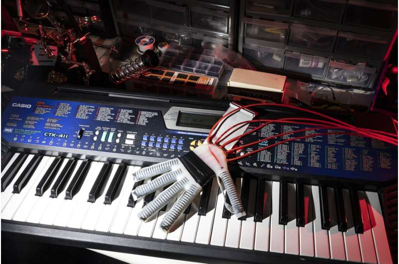
    A lightweight, flexible, multi-layered robo-glove that was 3D printed by Lin and colleagues is what they call a “smart hand exoskeleton” and has undergone testing. It weighs only 191g. The glove’s entire palm and wrist region is meant to be flexible and soft, and its shape may be adjusted to fit the anatomy of each wearer.

    Its fingertips have soft pneumatic actuators that provide motion and exert force, simulating the actions of a human hand. 16 flexible sensors, known as “taxels,” are also present in each fingertip, providing the wearer’s hand with tactile feedback when it comes into contact with items or surfaces. All actuators and sensors are installed through a single molding process, making glove production simple. Human users have considerable control over each finger’s movement while wearing the glove, according to senior author Dr. Erik Engeberg, a professor in the Department of Ocean & Mechanical Engineering at Florida Atlantic University.

    The glove’s purpose is to support and improve the wearer’s natural hand movements by giving them control over finger flexion and extension. The glove offers support and increases dexterity while also offering hand guiding. The scientists speculate that patients may eventually don a set of these gloves to aid in the autonomous recovery of motor skills, coordination, and dexterity in both hands.

    You can get the full details of this post in the link below:

    Techexplro

    Read More

  • Global Metric Created For The Development of Agile Robots

    Global Metric Created For The Development of Agile Robots

    The design and use of robots for reachability and dexterity during eye surgery have been specified by a collaborative study between academics from Moorfields Eye Hospital, University College London (UCL), and Kings College London (KCL). This is what is known as global metric created for the development of agile robots.

    “While there has been no work on designing robots for dexterity, that is, for reaching a specific point but under every orientation possible, we already have good algorithms for the reachability of robots that explain how long, stiff, or bendy a robot should be to reach specific locations,” said Dr. Christos Bergeles. An application that specifies reachability and dexterity has been developed by researchers Dr. Christos Bergeles from the School of Biomedical Engineering & Imaging Sciences, Dr. Konrad Leibrandt, formerly at UCL, and Prof. Lyndon da Cruz from Moorfields Eye Hospital. They have developed a global metric that makes it possible to compare continuous robots in terms of numbers.

    “While there has been no work on designing robots for dexterity, that is, for reaching a specific point but under every orientation possible, we already have good algorithms for the reachability of robots that explain how long, stiff, or bendy a robot should be to reach specific locations,” said Dr. Christos Bergeles.

    An application that specifies reachability and dexterity has been developed by researchers Dr. Christos Bergeles from the School of Biomedical Engineering & Imaging Sciences, Dr. Konrad Leibrandt, formerly at UCL, and Prof. Lyndon da Cruz from Moorfields Eye Hospital. They have developed a global metric that makes it possible to compare continuous robots in terms of numbers.

    Bergeles is utilizing the methods outlined in a paper published last year, to develop micro-surgical robots that offer opportunities beyond conventional surgery. He aims to implement the design algorithms in robotics for eye surgery, under a new collaborative program from KCL, UCL and Moorfield.

    “The developed systems will revitalize surgery by improving practice and patient outcomes, supporting the vision of sight restoration, and presenting evidence for the role of new smart instrumentation technologies in the operating room,” said Bergeles.

    Get the full details of this in the link below:

    Techexplro

    Read More