Tag: home automation

  • IoT Smart Home With Bluetooth Voice Control & Energy Monitoring

    IoT Smart Home With Bluetooth Voice Control & Energy Monitoring

    The Future of Homes Is Smart

    Imagine walking into your house, saying “lights on”, and instantly seeing your room light up. Or checking your phone to see how much energy your appliances are consuming while sipping coffee in another city. That’s not science fiction anymore—it’s the beauty of IoT smart homes.

    IoT Smart Home With Voice Control And Energy Monitoring project
    IoT Smart Home With Voice Control And Energy Monitoring project

    In this project, we built a DIY IoT smart home model powered by an ESP32 dev board, Thingspeak server, and a custom-built mobile app with voice control. The setup doesn’t just control appliances like lights and fans—it also monitors energy consumption in real-time.

    This project design has two modes: The Auto Mode and User Control Mode. In the user control mode, the project design allows the user to control the home appliances in the model using the app buttons and also using voice control. Whereas, in the auto mode, the design uses the motion sensor in the project design and knows when someone has entered the home model. It turn on the light, the socket and the fan. However, the fan speed is regulated by the temperature in the home model.

    This post walks you through the hardware, software, wiring, energy monitoring techniques, and IoT integration. We’ll also explore how Bluetooth and WiFi work together in this system to make your home smarter than ever.

    You May Also Like to Read: How To Build An IoT Home Automation & Surveillance with ESP32 Cam, Arduino & Blynk

    Why Choose ESP32 for a Smart Home Project?

    The ESP32 is a two-in-one beast. It comes with WiFi and Bluetooth built-in, making it ideal for IoT applications.

    The ESP32 WROOM 32E development board used for the IoT Smart Home Project Design
    the esp32 wroom 32e

    But here’s the twist: while we wanted to use the ESP32’s built-in Bluetooth, it took up too much memory space. So instead, we paired the ESP32 with an external HC-05 Bluetooth module for smooth voice control, while still using the ESP32’s WiFi to connect with Thingspeak.

    This combination gave us the best of both worlds—Bluetooth for quick, offline voice commands, and WiFi for cloud-based IoT control and monitoring.

    See also: AI-Powered Crop Harvesting: Benefits and Challenges

    Hardware Components Used

    ESP32 Development Board

    The brain of the project, responsible for:

    • Reading sensor data.
    • Sending/receiving data from Thingspeak.
    • Handling Bluetooth communication with the HC-05.
    • Controlling actuators through relays.

    HC-05 Bluetooth Module

    HC-05 Bluetooth Module
    HC-05 Bluetooth Module

    This module handled all the Bluetooth voice commands coming from the mobile app. The Speech-to-Text (STT) feature of the app converted voice into text commands and sent them as strings to the ESP32 via HC-05.

    DS18B20 Temperature Sensor

    DS18B20 temperature sensor
    DS18B20 temperature sensor

    This sensor is used for the sole purpose of reading the temperature in the home model to regulate the fan speed during the auto mode. This Dallas Temperature sensor uses a 10K-Ohm resistor for it to work. And it would be very important to include it in the design.

    Relay Modules

    Single Channel Relay Module Pinout
    Single Channel Relay Module Pinout

    We used three single-channel relay modules to control:

    1. A tungsten bulb.
    2. An AC socket.
    3. A standing DC fan.

    Energy Monitoring Modules

    • ZMPT101B Voltage Transformer → measures AC voltage.
    • 5A Ring-Type Current Sensor → measures AC current.
      Together, they calculate power and energy consumption of the connected appliances.

    Other Supporting Components

    • JST header connectors for clean, easy wiring.
    • 6×6 inch pattress box to house the electronics.
    • A transparent wooden smart home model to showcase the appliances and sensors.

    The Circuit Diagram for The IoT Smart Home With Bluetooth Voice Control & Energy Monitoring

    THe schematic diagram for the IoT Smart Home With Voice Control and Energy monitoring
    THe schematic diagram for the IoT Smart Home With Voice Control and Energy monitoring

    The above is the schematic diagram of the IoT Smart Home With Bluetooth Voice Control & Energy Monitoring on the pictorial form (the breadboard form).

    Explanation of the Schematic Diagram

    THe schematic diagram for the IoT Smart Home With Voice Control and Energy monitoring_2
    The schematic diagram for the IoT Smart Home With Voice Control and Energy monitoring_2

    The circuit design uses a motion sensor, PIR motion sensor to put the home model in auto mode which turns on the lights and other needed appliances in the home. The project is built with the ESP32 board as shown in the schematic diagram. The Bluetooth module was connected using serial communication protocol. And we had 3 relay modules that were used to control the actuators in the design. A 5V power supply module was used to power the system while introducing the power through a switch when needed. The schematic is in both the pictorial or schematic, you can see more in the link in the description below.

    How the Smart Home Model Was Built

    Wiring and Soldering

    All major connections were soldered onto a veroboard, with JST headers making it easy to plug/unplug modules. Relays were wired to the ESP32 GPIO pins for appliance control.

    Enclosure

    casing and enclosure
    casing and enclosure

    The pattress box housed the ESP32, relays, HC-05, and sensors safely. For this, we used the old-fashion 6×6-inch type of box. We had to cut some openings though. We had an opening for the programming of the project design itself, that is to program the ESP32 dev. board.

    Also, the temperature sensor has an opening so that it can be placed outside the enclosure box. And for the current sensor and voltage sensor modules, they need to read the A.C voltage and the current sensor through the loads connected. The transparent wooden model represented the home, with space for the light bulb, fan, and socket.

    Software Side of Things

    Programming Environment

    We used the Arduino IDE to write and upload code to the ESP32. You can download the Arduino sketch here at my GitHub repository.

    Arduino Code for the ESP32

    // Include the libraries we need
    #include <OneWire.h>
    #include <DallasTemperature.h>
    #include <WiFi.h>
    #include "ThingSpeak.h" // always include thingspeak header file after other header files and custom macros
    #include "EmonLib.h"             // Include Emon Library
    EnergyMonitor emon1;             // Create an instance
    
    const char ssid[] = "Galaxy A51 917E";  // your network SSID (name)
    const char pass[] = "tosin@345";   // your network password 
    WiFiClient  client;
    
    // SoftwareSerial bluetoothSerial(13, 12);
    String voiceCommand;
    //parameters for energy
    float realPower, apparentPower, powerFactor, supplyVoltage, Irms, actualCurrent, actualVoltage;
    float actualPower, actualEnergy;
    
    const int pirPin = 26;
    const int socketPin = 2;
    const int lightBulbPin = 18;
    const int dcFanPin = 15;
    const int voltageSensorPin = 34;
    const int currentSensorPin = 35;
    //states to hold the voice and IoT inputs
    bool bulbState, socketState, dcFanState, autoSwitch;
    bool bulbState1, socketState1, dcFanState1;
    
    unsigned long counterChannelNumber = 2536471;
    unsigned long counterChannelNumber2 = 2558070;
    unsigned long readChannelNumber = 2558070;             // Channel ID  
    const char * myWriteAPIKey = "5NYF7DAJ5CPNOJW9";
    const char * myWriteAPIKey2 = "XWA4T3G0P2MKHGYY";
    const char * myCounterReadAPIKey = "UHVB76ZF2XX8EJVA"; // Read API Key
    const int FieldNumber1 = 1;  // The field you wish to read
    const int FieldNumber2 = 2;  // The field you wish to read
    const int FieldNumber3 = 3;
    const int FieldNumber4 = 4;
    
    int number, statusCode = 0;
    int field[4] = {2,3,4,5};
    //for temp sensor
    // Data wire is plugged into port 2 on the Arduino
    #define ONE_WIRE_BUS 4
    // Setup a oneWire instance to communicate with any OneWire devices (not just Maxim/Dallas temperature ICs)
    OneWire oneWire(ONE_WIRE_BUS);
    // Pass our oneWire reference to Dallas Temperature. 
    DallasTemperature sensors(&oneWire);
    float tempC;
    
    void setup() {
      Serial.begin(9600);
      sensors.begin();
      //begin the bluetooth connections
      // bluetoothSerial.begin(115200);
      WiFi.mode(WIFI_STA);   
      ThingSpeak.begin(client);  // Initialize ThingSpeak
      //the outputs and inputs
      pinMode(socketPin, OUTPUT);
      pinMode(lightBulbPin, OUTPUT);
      pinMode(dcFanPin, OUTPUT);
      pinMode(pirPin, INPUT);
      //turn them all off first
      digitalWrite(socketPin, LOW);
      digitalWrite(lightBulbPin, LOW);
      digitalWrite(dcFanPin, LOW);
    //use the emon lib to call the voltage and current parameters
      emon1.voltage(voltageSensorPin, 55.26, 1.7);  // Voltage: input pin, calibration, phase_shift
      emon1.current(currentSensorPin, 107.1);       // Current: input pin, calibration.
      //check if conected to wiFi connection 
      if(WiFi.status() != WL_CONNECTED){
        Serial.print("Attempting to connect to SSID: ");
        Serial.println(ssid);
        while(WiFi.status() != WL_CONNECTED){
          WiFi.begin(ssid, pass); // Connect to WPA/WPA2 network. Change this line if using open or WEP network
          Serial.print(".");
          delay(5000);     
        } 
        Serial.println("\nConnected.");
      }
    }
    
    //function for check A.C voltage level
    double voltageCurrentSensors(){
      emon1.calcVI(20,2000);         // Calculate all. No.of half wavelengths (crossings), time-out
      //emon1.serialprint();           // Print out all variables (realpower, apparent power, Vrms, Irms, power factor)
      
      realPower       = emon1.realPower;        //extract Real Power into variable
      apparentPower   = emon1.apparentPower;    //extract Apparent Power into variable
      powerFactor     = emon1.powerFactor;      //extract Power Factor into Variable
      supplyVoltage   = emon1.Vrms;             //extract Vrms into Variable
      Irms            = emon1.Irms;             //extract Irms into Variable
      actualCurrent = (Irms/0.707)/1000;
      actualVoltage = supplyVoltage/0.707;
      actualPower = actualCurrent*actualVoltage;
      actualEnergy = actualPower* (millis()/1000);
      return actualCurrent, actualVoltage, actualPower, actualEnergy, powerFactor;
    }
    
    float tempSensor(){
      // call sensors.requestTemperatures() to issue a global temperature 
      // request to all devices on the bus
      // Serial.print("Requesting temperatures...");
      sensors.requestTemperatures(); // Send the command to get temperatures
      // Serial.println("DONE");
      // After we got the temperatures, we can print them here.
      // We use the function ByIndex, and as an example get the temperature from the first sensor only.
      tempC = sensors.getTempCByIndex(0);
    
      // Check if reading was successful
      if(tempC != DEVICE_DISCONNECTED_C) {
        Serial.print("Temperature for the device 1 (index 0) is: ");
        Serial.println(tempC);
      } 
      else  {
        Serial.println("Error: Could not read temperature data");
      }
    //put condition for turning on Fan Automatically using temperature
    if(tempC <= 10.20){
      digitalWrite(dcFanPin, LOW);
    }
    
    else if(tempC >= 55.00){
      digitalWrite(dcFanPin, HIGH);
    }
      return tempC;
    }
    
    float DecimalRound(float input, int decimals){
      float scale=pow(10,decimals);
      return round(input*scale)/scale;
    }
    
    void writeToThingspeak(){
      voltageCurrentSensors();
      actualVoltage = DecimalRound(actualVoltage, 2);
      actualCurrent = DecimalRound(actualCurrent, 2);
      actualPower = DecimalRound(actualPower, 2);
      actualEnergy = DecimalRound(actualEnergy, 2);
       // set the fields with the values , , , , powerFactor
      ThingSpeak.setField(1, actualVoltage);
      ThingSpeak.setField(2, actualCurrent);
      ThingSpeak.setField(3, actualPower);
      ThingSpeak.setField(4, actualEnergy);
       /*print out the values*/
       Serial.print("Voltage: ");
      Serial.print(actualVoltage);
      Serial.print(" current: ");
      Serial.println(actualCurrent);
       // write to the ThingSpeak channel
      int x = ThingSpeak.writeFields(counterChannelNumber, myWriteAPIKey);
      if(x == 200){
        Serial.println("Channel update successful.");
      }
      else{
        Serial.println("Problem updating channel. HTTP error code " + String(x));
      }
      
      // change the value
      // number++;
      // if(number > 99){
      //   number = 0;
      // }
      }
    
    int readFromThingspeak(){
      //---------------- Channel 1 ----------------//
      bulbState = ThingSpeak.readLongField(readChannelNumber, FieldNumber1, myCounterReadAPIKey);
      statusCode = ThingSpeak.getLastReadStatus();
          if (statusCode == 200){
            Serial.print("A.C. Bulb: ");
            Serial.println(bulbState);
          }
          else{
            Serial.println("Unable to read channel / No internet connection");
          }
      delay(100);
      //---------------- Channel 2 ----------------//
      socketState = ThingSpeak.readLongField(readChannelNumber, FieldNumber2, myCounterReadAPIKey);
      statusCode = ThingSpeak.getLastReadStatus();
      if (statusCode == 200) {
        Serial.print("A.C. Socket: ");
        Serial.println(socketState); 
      }
      else {
        Serial.println("Unable to read channel / No internet connection");
      }
      delay(100);
       //---------------- Channel 3 ----------------//
      dcFanState = ThingSpeak.readLongField(readChannelNumber, FieldNumber3, myCounterReadAPIKey);
      statusCode = ThingSpeak.getLastReadStatus();
      if (statusCode == 200) {
        Serial.print("DC Fan: ");
        Serial.println(dcFanState); 
      }
      else {
        Serial.println("Unable to read channel / No internet connection");
      }
       //---------------- Channel 4 ----------------//
      autoSwitch = ThingSpeak.readLongField(readChannelNumber, FieldNumber4, myCounterReadAPIKey);
      statusCode = ThingSpeak.getLastReadStatus();
      if (statusCode == 200) {
        Serial.print("Auto Switch Control: ");
        Serial.println(autoSwitch); 
      }
      else {
        Serial.println("Unable to read channel / No internet connection");
      }
      //use what is read to control appliances if the automatic switch is not turned on
    if(autoSwitch == 0){ 
    if(bulbState == 1){
      digitalWrite(lightBulbPin, HIGH); 
          }
    if (bulbState == 0) {
      digitalWrite(lightBulbPin, LOW);
        }
        //control the socket point
    if(socketState == 1){
      digitalWrite(socketPin, HIGH);
          }
    if (socketState == 0) {
      digitalWrite(socketPin, LOW);
        }
    if(dcFanState == 1){
      digitalWrite(dcFanPin, HIGH);
          }
    if (dcFanState == 0) {
      digitalWrite(dcFanPin, LOW);
        }
      }
      if(autoSwitch == 1){
         Serial.println(digitalRead(pirPin));
        if(digitalRead(pirPin) == 1){
         digitalWrite(lightBulbPin, HIGH);
          delay(2000);
          digitalWrite(dcFanPin, HIGH);
          delay(2000);
          digitalWrite(socketPin, HIGH);
        }
      }
      return dcFanState, socketState, bulbState;
    }
    
    //function for checking bluetooth voice control
    void btVoiceControl() {
      tempSensor();
      readFromThingspeak();
      while (Serial.available()) {
        delay(10);
        char c = Serial.read();
        if (c == '#') {
          break;
        }
        voiceCommand += c;
        // Serial.write(c);
      }
      if (voiceCommand.length() > 0) {
         Serial.println(voiceCommand);
    
        if((voiceCommand == "turn light on") || (voiceCommand == "light on") || (voiceCommand == "light bulb on")  || (voiceCommand == "turn bulb on") || (voiceCommand == "bulb on")|| (voiceCommand == "turn bob on") || (voiceCommand == "Bob on")){
          bulbState1 = 1;
        }
    
        if((voiceCommand == "turn light off") || (voiceCommand == "lights off") || (voiceCommand == "light bulb off") || (voiceCommand == "turn bulb off") || (voiceCommand == "bulb off") || (voiceCommand == "turn bob off") || (voiceCommand == "Bob off")){
          bulbState1 = 0;
        }
    
        if((voiceCommand == "turn socket on") || (voiceCommand == "socket on")){
          socketState1 = 1;
        }
    
        if((voiceCommand == "turn socket off") || (voiceCommand == "socket off")){
          bulbState1 = 0;
        }
    
        if((voiceCommand == "turn fan on") || (voiceCommand == "fan on")){
          dcFanState1 = 1;
        }
    
        if((voiceCommand == "turn fan off") || (voiceCommand == "fan off")){
          dcFanState1 = 0;
        }
         if((voiceCommand == "turn off all") || (voiceCommand == "off all") || (voiceCommand == "off all appliances")){
          dcFanState1 = 0;
          bulbState1 = 0;
          socketState1 = 0;
        }
    
        if((voiceCommand == "turn on all") || (voiceCommand == "on all") || (voiceCommand == "on all appliances") || (voiceCommand == "on all loads")){
          dcFanState1 = 1;
          bulbState1 = 1;
          socketState1 = 1;
        }
        //use voice to control appliance
        if(bulbState1 == 1){
      digitalWrite(lightBulbPin, HIGH); 
          }
    if (bulbState1 == 0) {
      digitalWrite(lightBulbPin, LOW);
        }
        //control the light bulb
    if(socketState1 == 1){
      digitalWrite(socketPin, HIGH);
          }
    if (socketState1 == 0) {
      digitalWrite(socketPin, LOW);
        }
    if(dcFanState1 == 1){
      digitalWrite(dcFanPin, HIGH);
          }
    if (dcFanState1 == 0) {
      digitalWrite(dcFanPin, LOW);
        }
    //send these states to thingspeak
      ThingSpeak.setField(1, bulbState1);
      ThingSpeak.setField(2, socketState1);
      ThingSpeak.setField(3, dcFanState1);
       // write to the ThingSpeak channel
      int x = ThingSpeak.writeFields(counterChannelNumber2, myWriteAPIKey2);
      if(x == 200){
        Serial.println("Channel update successful.");
      }
      else{
        Serial.println("error updating channel");
      }
      }
        Serial.print("A.C. Socket: ");
        Serial.print(socketState); 
        Serial.print(" A.C. Bulb: ");
        Serial.print(bulbState); 
        Serial.print(" DC Fan: ");
        Serial.println(dcFanState); 
        
      voiceCommand = "";
      // return bulbState1, socketState1, dcFanState1;
    }
    
    
    void loop() {
      writeToThingspeak();
      btVoiceControl(); 
      
       delay(15000);
     
      // voltageSensor();
    }


    Explanation of The Arduino Source Code

    Programming the IoT home Automation Using Arduino IDE
    Programming the IoT home Automation Using Arduino IDE

    In programming the project design, we used the Arduino IDE for this purpose. We used some libraries for this program, and we declared which pin on the ESP32, the PIR motion sensor was connected to as well as other actuator input pins. We also stated some some Boolean variables to hold the states of the actuators like the lightbulb and socket. We wrote some custom functions in the program to take care of the things needed to be done. And since we were using thingspeak as our server, we needed to send sensor data to the Thingspeak platform on one channel and read the actuator states that is being command by the app buttons on another channel on Thingspeak. Lastly, we programmed the Bluetooth module to be able to convert Speech to text stings into specific commands that would change the states of the home model appliances in the design. Once we have coded all of these out, we can upload our code. Don’t worry, the Arduino code is free. Just check the link above, go to my GitHub repo to download the code free.

    Mobile App with MIT App Inventor

    The app was designed with MIT App Inventor, providing:

    • Voice Control using Speech-to-Text.
    • Buttons and switches for manual control.
    • IoT integration with Thingspeak for remote monitoring.
    Developing the App using MIT App Inventor
    Developing the App using MIT App Inventor

    The next thing on the list is to program and design the app. This was done using the MIT appinventor. But if you are here and you want this app. Just comment below and I would send it to you FREE.  We designed the app using the drag and drop widgets on the MIT appinventor platform, and once we were confortable with its design, we started with the code block side. And the included all the codes needed to work as expected. Also again, leave a comment and I will send you this app for free.

    Thingspeak IoT Dashboard

    We created two channels on Thingspeak:

    1. Data Channel: Sends voltage, current, and power readings from the ESP32 to Thingspeak, which the app fetches for display.
    2. Control Channel: Allows the app to send HIGH/LOW commands (1 or 0) to Thingspeak. The ESP32 reads this and actuates relays accordingly.

    This setup allowed the project to work as both a monitoring and control system.

    Voice Control Implementation

    How Speech-to-Text Works in the App

    When you press the mic button on the app and say “fan on”, the app converts your speech into text. Sometimes, due to accents or clarity, it may convert to “fan un”.

    The app then sends this string over Bluetooth to the ESP32. The ESP32 checks the string using conditional statements and executes the command.

    For example:

    • “fan on” → relay for fan turns on.
    • “light off” → relay for bulb switches off.

    It’s simple, fast, and doesn’t require internet.

    Energy Monitoring Explained

    Measuring Voltage and Current

    • The ZMPT101B measures the AC mains voltage.
    • The 5A current sensor measures the current flowing through the load.

    Calculating Power and Energy

    • Power (W) = Voltage × Current.
    • Energy (Wh) = Power × Time.

    Instead of an RTC module, we used Arduino’s millis()/1000 function to keep track of time. This reduced hardware costs while still giving us accurate energy monitoring.

    Answering Key Questions

    How does the ESP32 connect with Thingspeak?

    The ESP32 connects to WiFi and uses the Thingspeak API to send sensor data and fetch control values.

    Can you control home appliances with Bluetooth voice commands?

    Yes. The HC-05 Bluetooth module receives text commands from a voice-enabled mobile app and triggers relays connected to appliances.

    What’s the best way to measure energy in a smart home project?

    A combination of a voltage sensor (ZMPT101B) and a current sensor (ACS712 or 5A ring sensor) works well for accurate energy calculations.

    Do I need an RTC module for energy monitoring?

    Not always. You can use the Arduino millis() function to track elapsed time and calculate energy consumption.

    What are the advantages of combining WiFi and Bluetooth in IoT projects?

    WiFi provides cloud connectivity, while Bluetooth allows offline, low-latency control. Using both gives redundancy and flexibility.

    Integrating All of It Together

    IoT smart home monitoring with ESP32

    This project is a perfect demonstration—one board, multiple features: Bluetooth, WiFi, IoT, and energy monitoring.

    Best app platform for IoT smart homes

    MIT App Inventor is beginner-friendly, but you can also upgrade to Flutter, React Native, or Android Studio for more advanced apps.

    Thingspeak dashboard for smart home control

    The dual-channel setup in Thingspeak makes it a lightweight yet powerful backend for real-time IoT systems.

    Benefits of This Smart Home Project

    • Voice control gives hands-free convenience.
    • Dual Mode Function: As the project works on both automatic mode where it runs everything using its predefined set parameters
    • Energy monitoring helps you understand and reduce power usage.
    • IoT integration enables remote monitoring from anywhere.
    • Low-cost setup compared to commercial smart home systems.
    • Scalable—you can add more relays, sensors, or even automation rules.

    Limitations and Challenges

    • Voice recognition errors due to accent/speech variations.
    • ESP32’s limited memory for Bluetooth tasks.
    • Power calibration needed for accuracy.
    • Relays are electromechanical and can wear out over time.

    Future Improvements

    • Use ESP32’s internal Bluetooth with memory optimization.
    • Add temperature and motion sensors for automation.
    • Upgrade to solar-powered operation for sustainability.
    • Implement AI-based voice recognition for better accuracy.
    • Replace Thingspeak with MQTT + Node-RED for more control.

    Conclusion – A Step Toward the Future

    This project shows how affordable hardware and DIY ingenuity can bring the concept of smart homes to life. By combining ESP32, relays, sensors, Bluetooth, and IoT dashboards, we created a model that not only controls appliances but also tracks energy use.

    And the best part? You don’t need to be an engineer to build it. With some patience, creativity, and the right tools, you can make your home smarter—one relay at a time.

    FAQs

    Can this system work without internet?

    Yes, the Bluetooth voice control works without internet. But the IoT features need WiFi.

    Can I expand the system to more appliances?

    Definitely. Just add more relays and update the code.

    How accurate is the energy monitoring?

    With calibration, you can achieve good accuracy, usually within ±5%.

    Is the MIT App Inventor app customizable?

    Yes, you can add more buttons, labels, or even redesign the interface.

    Can I use this project in a real house?

    Yes, but ensure proper insulation, safety relays, and certified electrical enclosures for real AC mains.

  • How To Build An IoT Home Automation & Surveillance with ESP32 Cam, Arduino & Blynk

    How To Build An IoT Home Automation & Surveillance with ESP32 Cam, Arduino & Blynk

    Introduction

    Imagine being able to switch off your lights, monitor your room, or get notified about smoke hazards right from your phone. Sounds futuristic? Not anymore. With just a few affordable components and a bit of DIY spirit, you can build your own IoT home automation and surveillance system using Arduino, ESP32-Cam, and the Blynk app. In this post, I’ll walk you through a real-life project I built that combines smart control and surveillance into one powerful setup.

    IoT Home Automation and surveillance system

    Whether you’re a curious tinkerer or someone looking for practical home automation, you’re going to love this guide.

    Required Hardware & Tools

    Before we dive into the connections and code, let’s quickly run through what you’ll need:

    Components:

    NodeMCU ESP8266 module used for the project design
    We used the Smoke sensor module (MQ-2) to sense smoke or dangerous gas concentrations in the project
    • 1x Smoke sensor module (MQ-2 or MQ-135)
    • 2x Single-channel solid state relay module
    • 1x Light bulb (A.C powered)
    • 1x Socket or extension switch
    • 4x JST connection wires
    • Veroboard
    • Power supply (5V DC regulated)

    Software:

    Circuit Wiring & Connections

    The schematic diagram for the design
    The schematic diagram for the design

    Explanation of The Schematic Diagram

    The schematic diagram shown above used both the NodeMCU (ESP8266-12E) and the ESP32 Cam development boards to accomplish the tasks of the project. The ESP32 Cam was connected only to the 5V DC power rails. We used this to only stream online video feeds. This is because, we didn’t wants an IO pin connections to any sensor or actuators to interrupt the real time video streaming.

    Let’s break down how the system is wired:

    NodeMCU:

    The pictorial form of the schematic diagram

    The pictorial or breadboard view of the schematic diagram shown above shows a separate connection of the relay modules using transistor and single solid state relays for them. In reality, the single channel solid state relay comes as a module and you just do your connection with ease.

    As of the time when this schematic diagram was drawn on Fritzing, there was no single part of module representation for the single channel solid state relay. The summary of the connection can be stated as:

    • Relay Module 1: Connected to D6 (controls A.C light). This was used to turn or or off the light-bulb from the Blynk app at will by the user. Since the D6 pinout of the NodeMCU output a logic voltage of 3.3V, the relay module itself used a logic “ON” stage of 3.3V and 0V for “OFF” hence why we chose it.
    • Relay Module 2: Connected to D7 (controls A.C socket). As the first relay module was connected, we also followed the same procedures but this time the input pin of the relay module was connected to the D7 pin on the NodeMCU.
    • Smoke Sensor: Connected to A0 (analog input). Since this module itself has an analog output. The only analog pinout on the NodeMCU was the A0 pin and we connect the analog output pin of the smoke sensor to this pin.
    • DC Fan: The DC fan was controlled via PWM on D5 through the TIP41C transistor in common emitter configuration

    ESP32-Cam:

    • Powered through a regulated 5V line
    • Connected to USB-Serial adapter for programming (TX-RX cross, GND-GND)
    Disassembling the DC fan to take the needed parts for the project work

    Tip: Make sure the grounds of all modules are connected together. Power the relay modules separately if you’re experiencing reboot issues. Also, the DC fan was disassembled as shown in the image above. We needed only the DC motor and the fan blades connected to it. So we disassembled DC hand fan and used the only needed parts inside.

    Code & Blynk App Setup

    Let’s now bring our project to life. This would mean that we need to set up the Blynk dashboard. It is very important to note that the Blynk version used to develop this project was the Blynk legacy. That version has long been discontinued. That said, the project can still work on the new Blynk IoT version.

    Setting Up the Blynk App:

    creating a new device on Blynk IoT
    • Download Blynk App: You can follow the link here to down the Blynk app. Of course, you would have to first signup if you haven’t yet. For the Blynk IoT, you would have to set up the project. By adding a New Device, Create New, etc. Read this IoT Based Gas Leak Detection Project to know how to do this.
    adding a new device to Blynk IoT
    adding a new device to Blynk IoT

    Using the Blynk Legacy version, you have to select “New Project” on the Mobile App. But using the Blynk IoT version. Click on the “+” button next and you need to click on the settings icon and follow the steps below next.

    • Create a new project and choose NodeMCU or ESP8266 as the device.
    • Add widgets: buttons for relays, gauge for smoke sensor, and video widget
    • Copy your Auth Token and save it for the Arduino sketch.
    Step 2: Naming the project on the Blynk App

    On the Blynk Legacy, you can name your project, select the Device you are running the project under the input box where the title is. Using the Blynk IoT version, you would have to input the title of project in the “Template Name” input box. After which you can click “continue” below.

    Screenshot of the widgets all added in the Blynk Legacy version
    Screenshot of the widgets all added in the Blynk Legacy version

    We needed the two button switched; one to control the light bulb and this was labelled “Bulb” and the other one is to control the socket. This was labelled “Socket”. The vertical slider labelled “Fan” was used to send PWM pulses to the GPIO on the NodeMCU and we used the gauge widget to show the percentage of the smoke reading concentration within the vicinity. And we added a notifier widget in between that would trigger in-app alerts.

    The same also goes for using the Blynk 2.0; you can pick and align the widgets from the list of widgets in the widget box dropdown menu. The video streaming widget is free so you don’t have to worry about paying.

    Programing the Project Design: Arduino Sketch Overview

    • The NodeMCU reads smoke levels from the analog pin
    • The NodeMCU controls relays and fan using digital and PWM pins
    • Sends smoke data and receives commands via Blynk
    • Sends notification when smoke level crosses threshold
    • The ESP32 Cam video is streamed on the video streaming widget on the Blynk app.

    During the programing of the project design using Arduino IDE, we programmed both development boards separately. The ESP32 Cam was programmed using its own programming board whereas the NodeMCU was programmed as it is.

    Arduino Code for NodeMCU:

    #define BLYNK_PRINT Serial
    
    #include <ESP8266WiFi.h>
    #include <BlynkSimpleEsp8266.h>
    
    // You should get Auth Token in the Blynk App.
    // Go to the Project Settings (nut icon).
    char auth[] = "EExmWR-3B8jC7H0ttOzr9qmtAciGW8DR";
    
    // Your WiFi credentials.
    // Set password to "" for open networks.
    char ssid[] = "Arinze";
    char pass[] = "ArinzePassword";
    
    int fanPin = D5;
    int fanWidget;
    int gasSensor = A0;
    int readGasSensor;
    
    BlynkTimer timer;
    
    void myTimerEvent(){
      //create a variable to read the gas sensor
      readGasSensor = analogRead(gasSensor);
        //first map the readings to 100% max.
      readGasSensor = map(readGasSensor, 0, 1023, 0, 100);
      //push it to the widget on blynk app
      Blynk.virtualWrite(V5, readGasSensor);
      //use control flow to check when to send an alert
    if(readGasSensor >= 60){
       Blynk.notify("THERE IS SMOKE SENSED, CHECK FOR FIRE"); 
    }
    else{
      
    }
    }
    
    BLYNK_WRITE(V1) {
    fanWidget = param.asInt();
    
    analogWrite(fanPin, fanWidget);
    }
    
    
    void setup()
    {
      // Debug console
      Serial.begin(9600);
      pinMode(fanPin, OUTPUT);
      pinMode(gasSensor, INPUT);
    
      Blynk.begin(auth, ssid, pass);
      // You can also specify server:
      //Blynk.begin(auth, ssid, pass, "blynk-cloud.com", 80);
      //Blynk.begin(auth, ssid, pass, IPAddress(192,168,1,100), 8080);
     timer.setInterval(1000L, myTimerEvent);
    }   
    
    void loop()
    {
      Blynk.run();
      timer.run();
     }


    Explanation of the NodeMCU Arduino Code

    The Arduino code above is pretty simple; this Arduino code is designed to create a simple home safety and automation system using an ESP8266 board and the Blynk platform. At its core, the program connects the ESP8266 to a Wi-Fi network and a Blynk project. By defining Blynk’s authentication token (auth) and the Wi-Fi credentials (ssid and pass), the code establishes a connection that allows the microcontroller to communicate with the Blynk app on a smartphone. This connection is the foundation for both monitoring a gas sensor and controlling a fan, enabling remote interaction with the physical hardware.

    IoT Home Automation: code snippet for the Arduino program

    The code features two primary functions: a BlynkTimer event for sensor monitoring and a Blynk write handler for remote fan control. The myTimerEvent function runs every second and reads data from a gas sensor connected to pin A0. It then converts the raw sensor data (from 0-1023) into a percentage (0-100) using the map() function. This converted value is sent to a virtual pin V5 in the Blynk app, allowing a user to see the gas level in real-time. Additionally, the code includes a safety feature: if the gas reading exceeds 60%, it automatically sends a push notification to the user’s phone with a warning message, acting as a simple gas and smoke alarm.

    IoT Home Automation: The Arduino code setup function

    The fan control functionality is handled by the BLYNK_WRITE(V1) block. This specific function is a Blynk handler that listens for changes from a widget (like a slider) attached to virtual pin V1 in the Blynk app. When a user adjusts this widget, its value is sent to the ESP8266, stored in the fanWidget variable, and then used to set the speed of a fan connected to digital pin D5. This allows a user to remotely turn the fan on or off, or even control its speed, all from their phone. The setup() function initializes the necessary hardware pins and establishes the Blynk connection, while the loop() continuously checks for new Blynk and timer events to ensure everything runs smoothly.

    Live Streaming Feature

    One of the coolest parts of this project is the video stream. To make the project on a localhost, you can just use the ESP32 Cam video stream. But to truly make it stream over IoT using Google Cloud Virtual Machines (VM), you would need to used node.JS and since npm comes bundled with Node.js, npm would install Express into a folder of your choice if you want.

    Step 1: Install Node.js (which includes npm)

    download node.js from official website
    download node.js from official website

    Download the node.JS from its official website and proceed to installing the Windows installer file (.msi) as shown above. IF you are using other OS, there should be option for you to do this also.

    installing node.js onto your PC
    installing node.js onto your PC

    Next, after the successful download, open the .exe file and click on install. Accept the license agreement and click “next” until you can be able to successfully install the node.js onto your PC. You can also choose to specify which folder you want the installation to take place too.

    Step 2: Creating the Web Socket Using Command Prompt

    Upon successful installation, you are ready then to move to the next level which is testing if the node.JS and npm was installed successfully. To do this, open your command prompt as an admin. Type “cmd” in your state menu and select open as an administrator.

    After this is opened, type the following command:
    node -v
    npm -v
    The above following syntax would prompt your PC to show the node.js version installed on the PC and the npm version too.

    We would proceed to create a folder next. For us here, we created our own web socket folder inside the Arduino folder and name it ESP32 Cam Web Socket. Select this folder from your Command prompt by type the command “cd yourFolderPath”.

    installing express on the ESP32 cam folder

    In this selected folder we can install the express locally on this folder. By typing first: npm init -y
    After it has finished executing that, you can type the command next:
    npm install express
    And that is it for that. Next is to create two important files: the server.js file and client.html file. We can either use the simpler way of creating this file using a simple text editor like notepad; dragging and dropping it into the folder itself or just creating it directory using the cmd. I used the shortcut of creating the files using the cmd option. By simply typing the syntax:
    type nul > server.js
    type nul > client.html

    creating the server.js file using command prompt

    These created the two files that I needed to proceed next in the following phase of the project design. The next phase would be to open these two files using VSCode editor or any other text editor of your preference. We would need to put in some code in them to make sure they work.

    the files created

    javascript code for the server.js file

    const path = require('path');
    const express = require('express');
    const WebSocket = require('ws');
    const app = express();
    
    const WS_PORT  = xxxx; // WebSocket server port
    const HTTP_PORT = xxx; // HTTP server port
    
    const wsServer = new WebSocket.Server({port: WS_PORT}, ()=> console.log(`WS Server is listening at ${WS_PORT}`));
    
    let connectedClients = [];
    wsServer.on('connection', (ws, req)=>{
        console.log('Connected');
        connectedClients.push(ws);
    
        ws.on('message', data => {
            connectedClients.forEach((ws,i)=>{
                if(ws.readyState === ws.OPEN){
                    ws.send(data);
                }else{
                    connectedClients.splice(i ,1);
                }
            })
        });
    });
    
    app.get('/client',(req,res)=>res.sendFile(path.resolve(__dirname, './client.html')));
    app.listen(HTTP_PORT, ()=> console.log(`HTTP server listening at ${HTTP_PORT}`));
    

    HTML Code for the Client Side

    <html>
        <head>
            <title>Client</title>
        </head>
        <body>
            <img src="">
            <script>
                const img = document.querySelector('img');
                const WS_URL = 'ws:///10.146.182.101:8888';
                const ws = new WebSocket(WS_URL);
                let urlObject;
                ws.onopen = () => console.log(`Connected to ${WS_URL}`);
                ws.onmessage = message => {
                    const arrayBuffer = message.data;
                    if(urlObject){
                        URL.revokeObjectURL(urlObject);
                    }
                    urlObject = URL.createObjectURL(new Blob([arrayBuffer]));
                    img.src = urlObject;
                }
            </script>
        </body>
    </html>
    

    For the ws_URL, the IP address would have to be the IP address of your PC. preferably a static IP address. Add the port of that as define in the server.js file.

    Open the Arduino file, you can download all the local host file from this GitHub file here. You can select the type of ESP32 Cam board that you are using and upload the code. Wait for it to successfully upload. Once this is done, you should open the serial monitor. And after a while, you will see it saying it is connected to the webserver. Copy the IP address on the serial monitor and paste it into any web browser tab and hit the enter key. And you can stream the video on the local host. This is ONLY POSSIBLE PROVIDED THE DEVICE WITH THE BROWSER IS CONNECTED TO THE WiFi NETWORK.

    How to Stream The Video Over the Internet Using Google Cloud Platform (GCP)

    login into your GCP account and go to compute engine.
    Select Virtual Machine Instance
    Click create and name the VM instance and use only lowercase letters
    Choose the location nearest to you (region)
    Choose a zone too.
    Since the server is for pushing small images from the esp32 cam client to other clients, we chose g1-small
    Under machine type, you can choose 1.7Gb memory
    under server choose Ubuntu 18.04 LTS
    Leave the rest as it is,
    Under firewall, check all the checkboxes
    select create after all of these are done.

    After that, connect the VM instance via SSH. And when this was connected, we can install the Node.js on this virtual machine.
    Create the project directory by typing “mkdir nodeServer”.
    Then go into that directory using the command “cd nodeSever”
    Once there you can list the files and directories there using the command “ls”
    use the command, curl -sL https://deb.nodesource.com/setup_10.x | sudo -E bash –

    Install node.js by typing ‘sudo apt install nodejs’ and key in “Y” when prompted to continue or not.
    You can check your node.js version or npm version after this. by typing node –version and npm –version

    As shown before, create two files; the client.html and the server.js file. Then use the Vi editor to open the server.js file. Just basically copy and past the code from the file below and change the port for http 80. GCP has has web socket port which is 65080. close the VI editor and save the code by typing “:q!”

    Creating Firewall Rules

    Next set up the firewall. and set the wirewall rules. Also use the VI editor to open the client.html file. copy and paste the code inside. Copy the external IP address from the VM instance and put in the code. put the port of the GCP and as shown in the local host code. THis would become your websocket address. save your file and exit. Then run the server.js by typing “sudo node server.js”

    How Do I Build a Surveillance Camera Using ESP32‑Cam and Blynk?

    Simple. First, flash the ESP32-Cam with streaming firmware. You can find examples in the Arduino IDE under ESP32 -> Camera -> CameraWebServer. Once that works:

    • Use Node.js to create a web socket that captures and relays the video
    • Host the stream on a Google Cloud VM
    • Place the video stream link inside the Blynk video widget

    Setting Up The Arduino Hardware Part

    You will need to disassemble the DC as pictured above and use the useful part of it.

    Once the DC hand fan has been disassembled, we can proceed to measure the voltage of the DC fan. The idea is to find out what is the maximum voltage that is powering the DC fan at its maximum speed. Once we are able to find out this voltage; we can be able to reverse engineer it using the control Widget from Blynk dashboard and also using the t.i.p.41C NPN transistor configuration. Using the multimeter instrument, and its reading set to the DC voltage measurement reading, we can see that the voltage of the DC fan when we crank up the speed by pressing the speed button 3 times. The measured voltage is displayed as 7.89 volts. We can set the supply voltage from the collector to range from 0 volts to 9 Volts.

    The USB soldering Iron works for us because we can just plug it into our PC USB port and use it to solder whatever we want to solder. However, the soldering iron itself came with its own solder. This is more flexible and softer to touch and it easily melt under the heat of the soldering Iron. The USB soldering iron has its own temperature regulation and we used the highest temperature for this job.

    Smoke Detection and Alerts

    Here’s where things get serious—safety first.

    How to Get Notifications with Images from ESP32‑Cam Using Blynk?

    Currently, Blynk doesn’t directly support image upload. But there’s a workaround:

    • Set ESP32-Cam to take a snapshot when smoke level exceeds 700 (or any value you choose)
    • Store it temporarily on the web socket server
    • Send notification with a clickable link to that image

    Meanwhile, NodeMCU is already triggering Blynk alerts when smoke levels are high.

    ESP32 Cam Motion Detection PIR Blynk Integration

    Want to spice up your system with motion detection?

    Add a PIR sensor to the ESP32-Cam. Modify the CameraWebServer code to start video or take a picture when motion is detected. Combine that with a notification using the Blynk HTTP API.

    ESP32 Cam Surveillance System Arduino Blynk

    This combo is powerful:

    • ESP32-Cam for vision
    • NodeMCU for actuator control and sensing
    • Blynk app for a unified control dashboard

    Together, they form a complete DIY surveillance system.

    Testing & Troubleshooting Tips

    Here are some roadblocks you may encounter:

    • ESP32-Cam Brownout: Use external 5V 2A supply
    • Camera Init Failed: Check GPIO pins and camera model selection
    • Relays Flickering: Separate power supplies
    • No Stream in Blynk: Check that your video link is HTTP (not HTTPS)

    Can Blynk Support Video Streaming from ESP32‑Cam?

    Yes, indirectly. Blynk’s video widget accepts HTTP streams. You’ll need to set up a web socket on a cloud server (like GCP or AWS) to serve the ESP32-Cam feed.

    Arduino ESP32 Cam Doorbell Security with Blynk

    Thinking ahead? You can build a smart doorbell system:

    • ESP32-Cam detects someone at the door (with PIR or push button)
    • Takes a picture or starts streaming
    • Sends notification to your phone via Blynk

    This can be a standalone future project too.

    Is ESP32‑Cam Secure for Home Surveillance Projects?

    It depends. ESP32-Cam doesn’t have built-in encryption. For sensitive surveillance:

    • Use strong Wi-Fi passwords
    • Restrict access to stream URL
    • Use VPN or secure tunnels like ngrok if exposing ports

    Enhancements & Future Extensions

    Here are some ideas to take things up a notch:

    • Face Recognition using ESP-WHO library
    • Node-RED Integration for automation workflows
    • Home Assistant Compatibility via MQTT
    • Sound Sensor to detect unusual sounds
    • Cloud Data Logging using Firebase or Thingspeak

    Conclusion

    That’s a wrap! With just an ESP32-Cam, NodeMCU, and Blynk, you’ve got a mini smart home setup right in your hands. You now control lights and sockets, monitor air quality, and stream live video—all from a single app.

    Don’t stop here. Tinker more, improve security, maybe add facial recognition or integrate with Alexa or Google Home. The possibilities are endless!

    FAQs

    1. Can I use Blynk with ESP32-Cam only, without NodeMCU?
    Yes, but you’ll need to modify the code to support Blynk library with ESP32. NodeMCU is used here to offload actuator control.

    2. Why does my ESP32-Cam keep rebooting?
    Likely a power issue. Use a stable 5V, 2A supply and ensure GPIO0 is correctly set during flashing.

    3. How can I make my stream private?
    Run it on a password-protected web server or use a VPN. Avoid exposing ports directly.

    4. Can I log smoke data somewhere?
    Yes! Integrate Firebase or Thingspeak in your NodeMCU code to log sensor values over time.

    5. Will this work on Blynk 2.0 (Blynk IoT)?
    Yes, with slight adjustments in widget settings and authentication. The basic logic remains the same.

  • The Governor’s daughter Free eBook

    The Governor’s daughter Free eBook

    The governor's daughter

    ”The Governor’s Daughter” is a captivating debut novel that delves into a dystopian world where Emma Bellamy, a nineteen-year-old, rebels against the oppressive regime she was born into. Emma is the daughter of the revered governor, a powerful figure in a society governed by White nationalists and a corrupt Universal Church. Frustrated by the archaic Purity Protocols and the suffocating patriarchy, Emma questions everything she’s been taught. When she discovers that her beliefs are based on lies, she embarks on a clandestine journey beyond the city walls. There, she encounters extreme poverty, unchecked police violence, and brave souls who dare to resist.

    The governor's daughter

    The central conflict revolves around Emma’s defiance of her father, the governor, and the oppressive system. As she seeks the truth, she challenges the committee’s reign, risking her safety and privilege.

    Main Characters

    The central character in “The Governor’s Daughter” is nineteen-year-old Emma Bellamy. Emma is no “good girl.” She rebels against the oppressive system that treats her like property, questions the suffocating patriarchy enforced by a corrupt Universal Church, and challenges her uber-powerful father, the revered Governor. Emma’s recalcitrant mind and headstrong nature drive her to seek the truth beyond the lies she’s been taught.

    Plot

    Set in the year 2045, the novel unfolds in a dystopian America. Emma’s journey begins when she disobeys the rigid Purity Protocols and ventures beyond the razor-wire topped walls of Premier City. There, she confronts the harsh reality faced by ninety-eight percent of the population: extreme poverty, disease, and unchecked police violence. The aftermath of a civil war in the ’20s has left the masses broken and dispirited, unable to challenge the Committee’s oppressive rule.

    Emma discovers a few brave souls who dare to resist, risking everything to live by their own rules. As she grapples with her choices, Emma must decide whether to accept an unfulfilled but privileged life or commit the ultimate act of rebellion for a future filled with purpose, passion, and freedom.

    Setting

    The story takes place in a bleak future America, where the White Nationalist government wields immense power. Premier City, surrounded by razor-wire walls, symbolizes oppression and inequality. The setting influences the characters’ struggles, emphasizing the stark contrast between privilege and suffering.

    Themes

    Several underlying themes emerge:

    1. Rebellion and Resistance: Emma’s defiance against oppressive systems reflects the human desire for autonomy and justice.
    2. Truth and Lies: Emma’s quest for truth challenges the propaganda fed to the masses, highlighting the importance of critical thinking.
    3. Inequality and Privilege: The stark divide between the privileged elite and the suffering majority underscores the consequences of unchecked power.
    4. Hope and Freedom: Emma’s journey represents hope for change and the pursuit of a better future.

    Read full novel here.

    Conclusion

    “The Governor’s Daughter” weaves a gripping narrative of rebellion, sacrifice, and the search for truth. Maria Ereni Dampman’s debut novel invites readers to question authority, challenge norms, and embrace the possible brighter future.

    Read More eBook.

  • Home Automation Simulation Using Arduino Proteus

    Home Automation Simulation Using Arduino Proteus

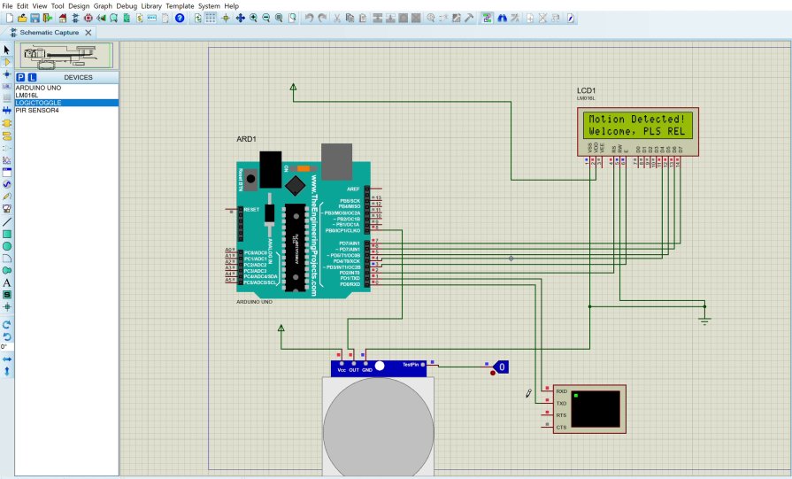
    In today’s post, we will be doing a simulation of of motion based home automation using PIR sensor, Arduino and Proteus circuit wizard. The passive infrared (P.I.R) sensor will be used to simulate the presence and absence of motion and this in turn will be used to control the state of an A.C light bulb, by turning on or off the relay connected to the AC bulb. And we note the state of each condition when displayed on the LCD, also printed on the serial console. Let us get into home automation simulation using Arduino, Proteus and PIR sensor.

    home automation simulation using Arduino, Proteus
    home automation simulation using Arduino, Proteus

    Proteus Design and Circuit Simulator Version

    The version of Proteus design and circuit simulator is Proteus version 8.13. you can find the can be downloaded from the Github link here and the libraries used for this tutorial. The Proteus version allowed us to quickly simulate this circuitry without paying for the Proteus app itself. Once download, you can unzip the folder and install the app itself.

    Home automation simulation

    Copy and Paste Proteus Libraries Into Proteus Library Folder

    After the successful installation of the app, the Proteus folder can be accessed to put the libraries that came with these file. For most installations this is found at the address C:\Program Files (x86)\Labcenter Electronics\Proteus 8 Professional\DATA\LIBRARY. For Windows’ users that is.

    Proteus library
    Proteus library

    When you are here, you can go back to where your library folders are and unzip all the libraries you need for this tutorial. Copy and paste them inside this location shown above. Once the this is done, close the folder and return to your Proteus app. Right click to run it as an admin.

    Running the Proteus in admin mode will give you permissions and access to control all aspects on the design and circuit simulation IDE.

    When the circuit IDE open, we will have the option to either be asked to create a new project. This is shown below.

    Home Automation simulation using Arduino and Proteus

    This place will show you the option of either opening an existing project, creating a new one or open an existing project. There is also the option of creating a new flowchart or open sample of it.

    Enter or choose the name you want for your project, for this tutorial, we tagged it “Home Automation Simulation“. Click next after that and keep clicking next until the simulation schematic capture background opens.

    Home automation simulation using Arduino Proteus

    Home Automation Simulation using Arduino Proteus: Selecting the Components

    Home Automation

    We selected this component selection symbol as shown above in 1, then picked the components themselves that we needed. We are using the Arduino Uno, the PIR sensor, the 1602 LCD, etc.

    component list in Proteus

    Position these components as they should be. And next this is to connect them. You can watch the YouTube video to get acquainted on how best to go about it.

    The final outlook would resemble the image above. You can add the virtual terminal as a way to see the serial prints of the Arduino Uno. This attached serial print for the home automation simulation using Arduino Proteus also as the admin backend side where he or she can see what is going on. The LCD connection here is done in the 4-bits mode using only 4 wires instead of the the 8 wires mode. The Vdd is connected to power and you can choose to put a +5V to it or not. It will work in the simulation. All ground pins of the components must be connected to the ground.

    Programming The Code (Arduino Sketch)

    Open up the Arduino IDE, look for the code that named simulation_1, downloaded from the Github page. Copy this code and paste it into the Arduino IDE. Please save this file.

    Arduino Compilier

    Before running this code, click on File, select Preference, make sure the Compile checkbox is checked or enabled. After that, click okay and proceed to verifying the Arduino sketch.

    Arduino Code Explanation

    Arduino sketch

    The sketch already has a comment lines explaining the code line. However, in summary, we displayed a welcome message in the setup() function. We created a custom function called turnOnBulb() which was used to turn on the light bulb and display on the LCD that the light has been turned on. Also, another turnOffBulb() function which was used to turn off the bulb and display this state on the LCD.

    Copying HEX code of Arduino Proteus

    Copy the HEX code address after successfully compiling the source code. This is found in the output console. Now take the HEX code address into the Proteus IDE and paste into into the Arduino Uno.

    When we double-click on the Arduino Uno, we can paste the HEX code in the program file address. After that, click OK. And the edit component box will disappear. Now, run your simulation.

    Home Automation Arduino Proteus

    Getting Unable to Open HEX File Error

    Home automation simulation using Arduino Proteus

    This type of error won’t allow the simulation to run. Because the PIR sensor has have access to its HEX file. To solve this, double-click on the on the PIR sensor, within the Program File address, double click on the file sign and navigate to the Proteus library.

    Proteus PIR HEX file

    You will find the PIR sensor HEX file the address in the library. Then select it, by double-clicking on it. The rest is just history afterwards. The program should be able to run effectively now.

    Home automation simulation using Arduino Proteus

    Conclusion

    When motion is sensed, our display show show something and the light bulb should come on otherwise, the lightbulb will be turned off and the LCD will display a message at each interval what is happening.

    Home automation simulation using Arduino Proteus: Simulating light bulb in proteus

    Read More