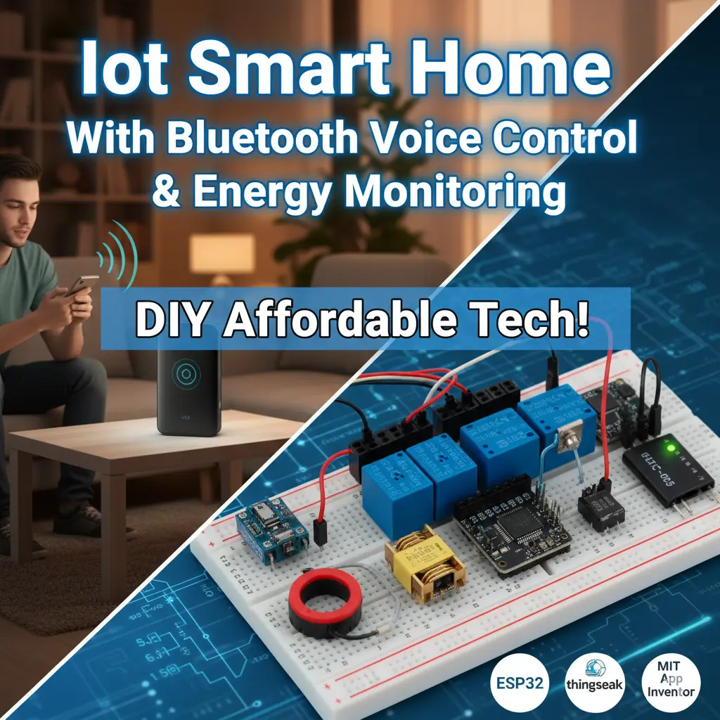
The Future of Homes Is Smart
Imagine walking into your house, saying “lights on”, and instantly seeing your room light up. Or checking your phone to see how much energy your appliances are consuming while sipping coffee in another city. That’s not science fiction anymore—it’s the beauty of IoT smart homes.
In this project, we built a DIY IoT smart home model powered by an ESP32 dev board, Thingspeak server, and a custom-built mobile app with voice control. The setup doesn’t just control appliances like lights and fans—it also monitors energy consumption in real-time.
This project design has two modes: The Auto Mode and User Control Mode. In the user control mode, the project design allows the user to control the home appliances in the model using the app buttons and also using voice control. Whereas, in the auto mode, the design uses the motion sensor in the project design and knows when someone has entered the home model. It turn on the light, the socket and the fan. However, the fan speed is regulated by the temperature in the home model.
This post walks you through the hardware, software, wiring, energy monitoring techniques, and IoT integration. We’ll also explore how Bluetooth and WiFi work together in this system to make your home smarter than ever.
You May Also Like to Read: How To Build An IoT Home Automation & Surveillance with ESP32 Cam, Arduino & Blynk
Why Choose ESP32 for a Smart Home Project?
The ESP32 is a two-in-one beast. It comes with WiFi and Bluetooth built-in, making it ideal for IoT applications.
But here’s the twist: while we wanted to use the ESP32’s built-in Bluetooth, it took up too much memory space. So instead, we paired the ESP32 with an external HC-05 Bluetooth module for smooth voice control, while still using the ESP32’s WiFi to connect with Thingspeak.
This combination gave us the best of both worlds—Bluetooth for quick, offline voice commands, and WiFi for cloud-based IoT control and monitoring.
See also: AI-Powered Crop Harvesting: Benefits and Challenges
Hardware Components Used
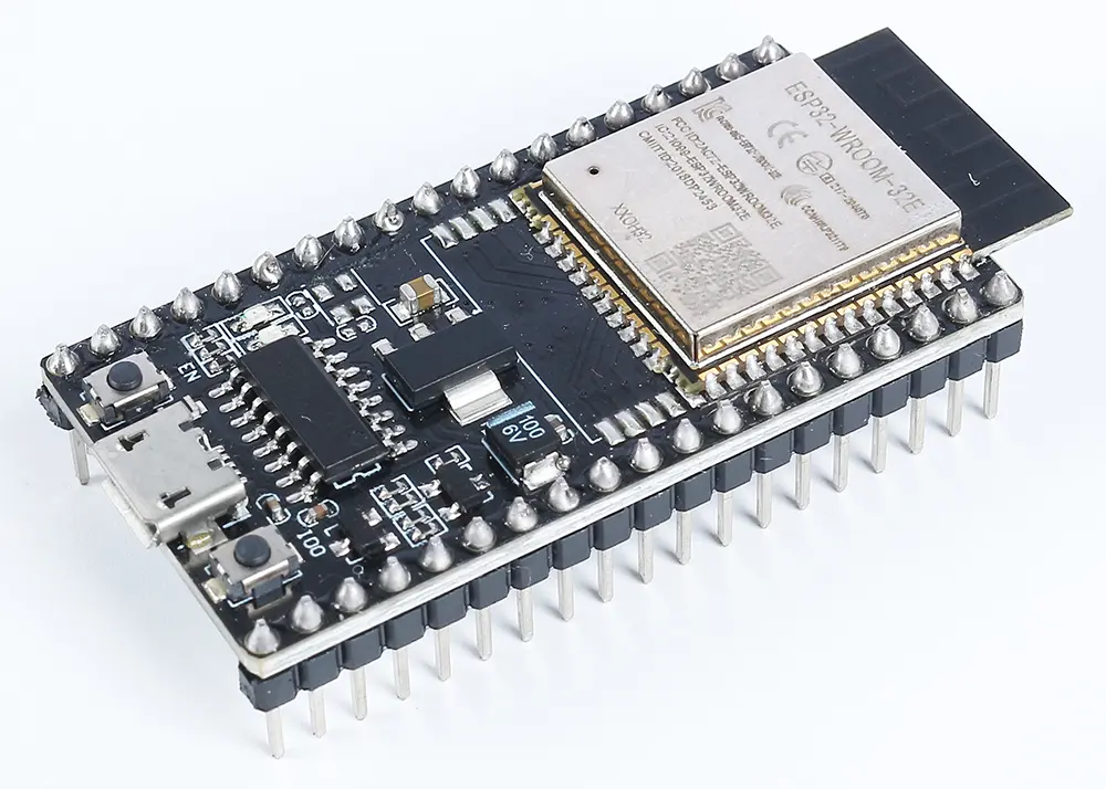
ESP32 Development Board
The brain of the project, responsible for:
- Reading sensor data.
- Sending/receiving data from Thingspeak.
- Handling Bluetooth communication with the HC-05.
- Controlling actuators through relays.
HC-05 Bluetooth Module
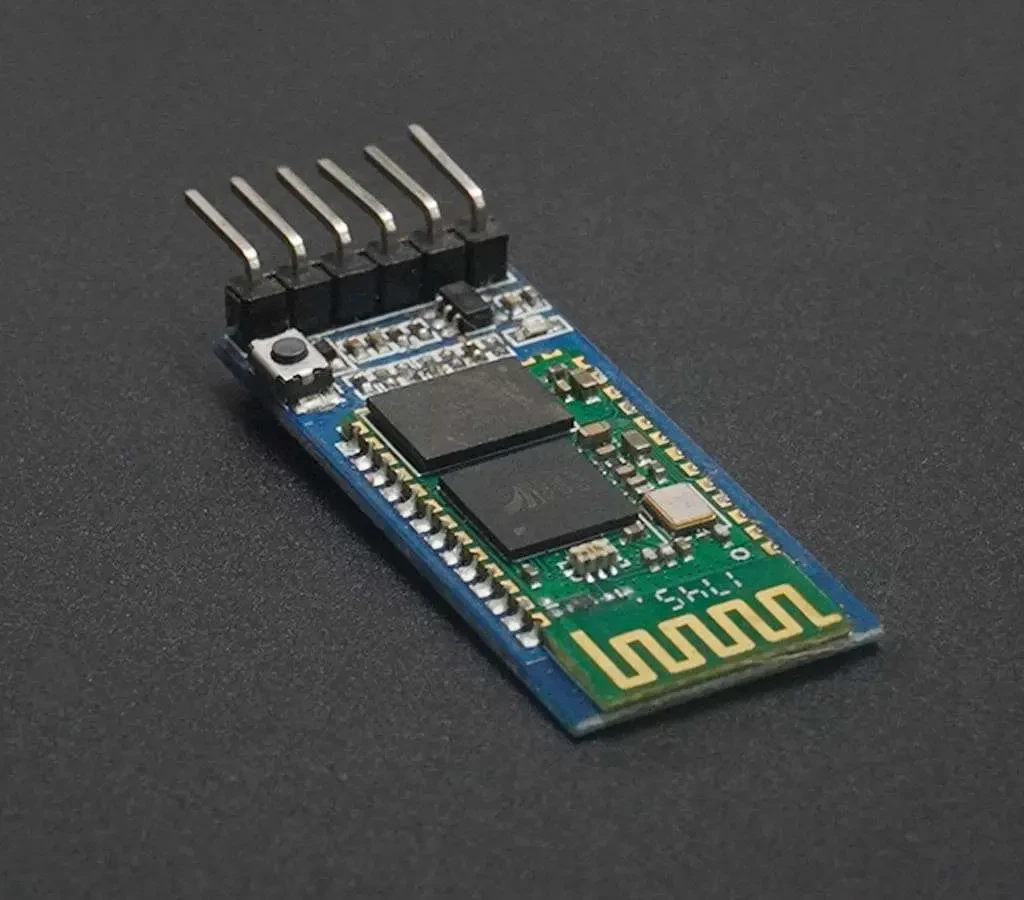
This module handled all the Bluetooth voice commands coming from the mobile app. The Speech-to-Text (STT) feature of the app converted voice into text commands and sent them as strings to the ESP32 via HC-05.
DS18B20 Temperature Sensor
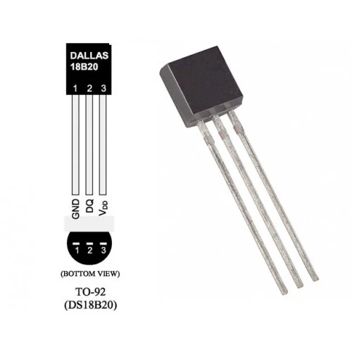
This sensor is used for the sole purpose of reading the temperature in the home model to regulate the fan speed during the auto mode. This Dallas Temperature sensor uses a 10K-Ohm resistor for it to work. And it would be very important to include it in the design.
Relay Modules
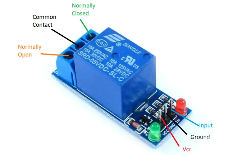
We used three single-channel relay modules to control:
- A tungsten bulb.
- An AC socket.
- A standing DC fan.
Energy Monitoring Modules
- ZMPT101B Voltage Transformer → measures AC voltage.
- 5A Ring-Type Current Sensor → measures AC current.
Together, they calculate power and energy consumption of the connected appliances.
Other Supporting Components
- JST header connectors for clean, easy wiring.
- 6×6 inch pattress box to house the electronics.
- A transparent wooden smart home model to showcase the appliances and sensors.
The Circuit Diagram for The IoT Smart Home With Bluetooth Voice Control & Energy Monitoring
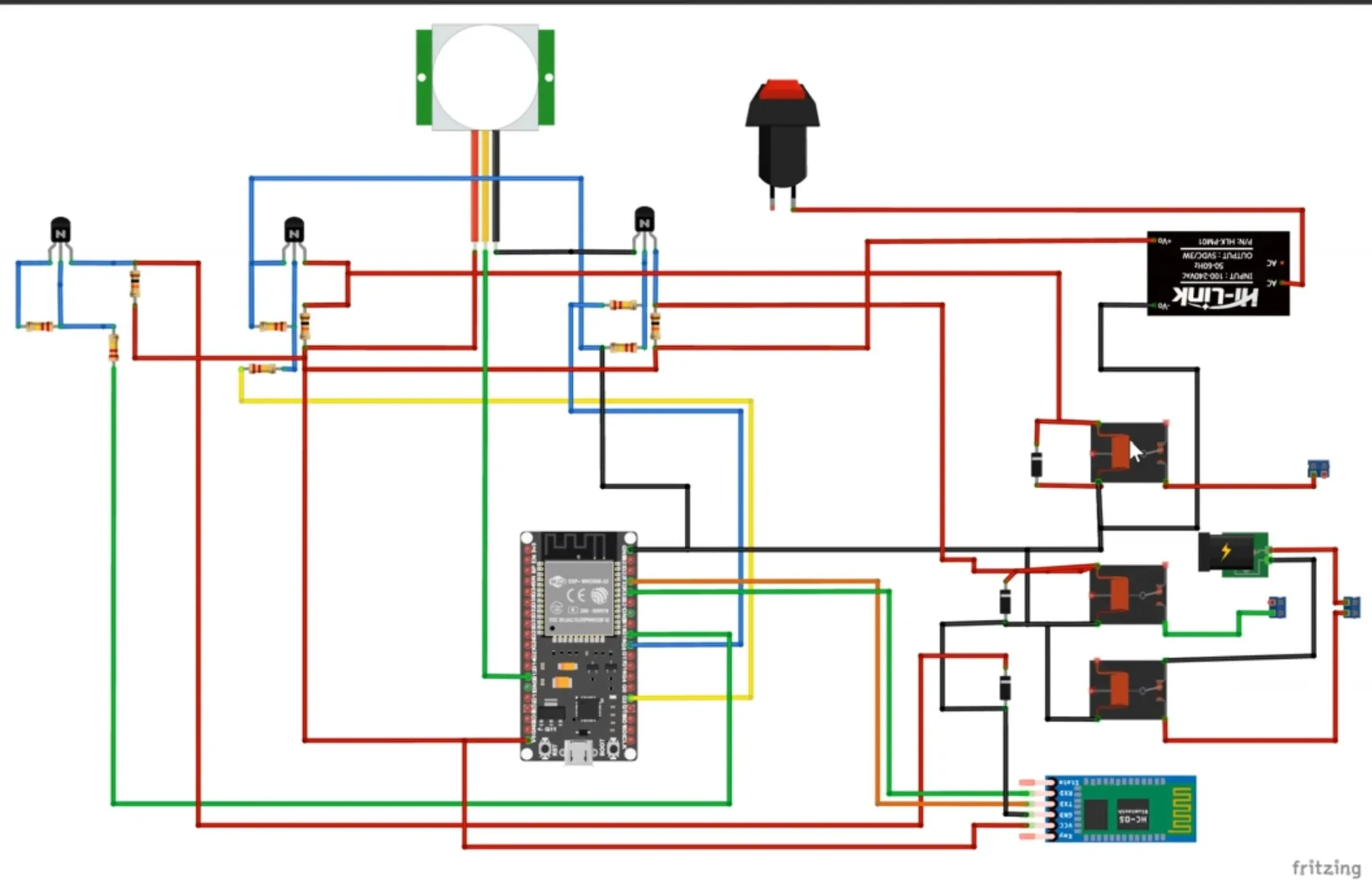
The above is the schematic diagram of the IoT Smart Home With Bluetooth Voice Control & Energy Monitoring on the pictorial form (the breadboard form).
Explanation of the Schematic Diagram
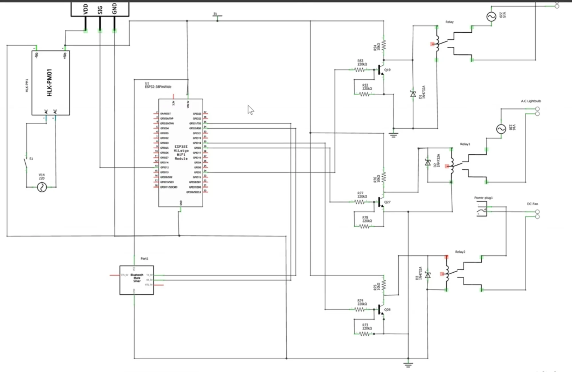
The circuit design uses a motion sensor, PIR motion sensor to put the home model in auto mode which turns on the lights and other needed appliances in the home. The project is built with the ESP32 board as shown in the schematic diagram. The Bluetooth module was connected using serial communication protocol. And we had 3 relay modules that were used to control the actuators in the design. A 5V power supply module was used to power the system while introducing the power through a switch when needed. The schematic is in both the pictorial or schematic, you can see more in the link in the description below.
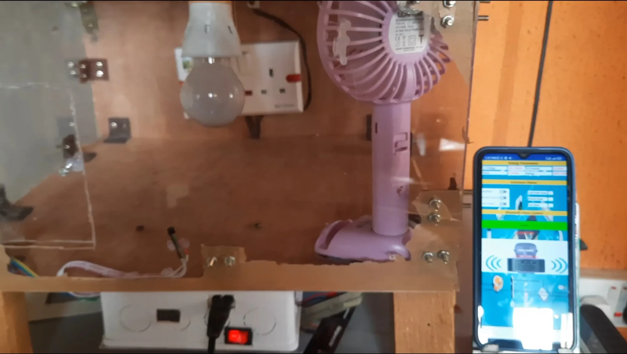
How the Smart Home Model Was Built
Wiring and Soldering
All major connections were soldered onto a veroboard, with JST headers making it easy to plug/unplug modules. Relays were wired to the ESP32 GPIO pins for appliance control.
Enclosure
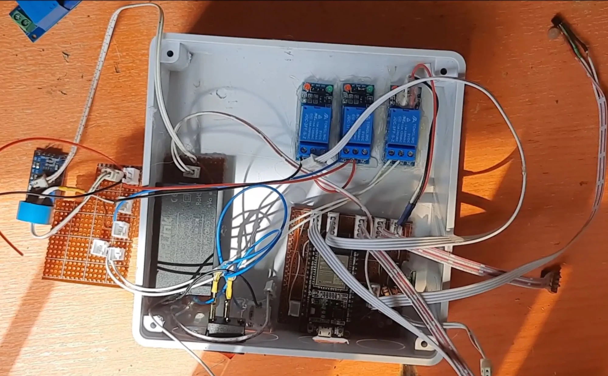
The pattress box housed the ESP32, relays, HC-05, and sensors safely. For this, we used the old-fashion 6×6-inch type of box. We had to cut some openings though. We had an opening for the programming of the project design itself, that is to program the ESP32 dev. board.
Also, the temperature sensor has an opening so that it can be placed outside the enclosure box. And for the current sensor and voltage sensor modules, they need to read the A.C voltage and the current sensor through the loads connected. The transparent wooden model represented the home, with space for the light bulb, fan, and socket.
Software Side of Things
Programming Environment
We used the Arduino IDE to write and upload code to the ESP32. You can download the Arduino sketch here at my GitHub repository.
Arduino Code for the ESP32
// Include the libraries we need
#include <OneWire.h>
#include <DallasTemperature.h>
#include <WiFi.h>
#include "ThingSpeak.h" // always include thingspeak header file after other header files and custom macros
#include "EmonLib.h"             // Include Emon Library
EnergyMonitor emon1;             // Create an instance

const char ssid[] = "Galaxy A51 917E";  // your network SSID (name)
const char pass[] = "tosin@345";   // your network password
WiFiClient  client;

// SoftwareSerial bluetoothSerial(13, 12);
String voiceCommand;
//parameters for energy
float realPower, apparentPower, powerFactor, supplyVoltage, Irms, actualCurrent, actualVoltage;
float actualPower, actualEnergy;

const int pirPin = 26;
const int socketPin = 2;
const int lightBulbPin = 18;
const int dcFanPin = 15;
const int voltageSensorPin = 34;
const int currentSensorPin = 35;
//states to hold the voice and IoT inputs
bool bulbState, socketState, dcFanState, autoSwitch;
bool bulbState1, socketState1, dcFanState1;

unsigned long counterChannelNumber = 2536471;
unsigned long counterChannelNumber2 = 2558070;
unsigned long readChannelNumber = 2558070;             // Channel ID
const char * myWriteAPIKey = "5NYF7DAJ5CPNOJW9";
const char * myWriteAPIKey2 = "XWA4T3G0P2MKHGYY";
const char * myCounterReadAPIKey = "UHVB76ZF2XX8EJVA"; // Read API Key
const int FieldNumber1 = 1;  // The field you wish to read
const int FieldNumber2 = 2;  // The field you wish to read
const int FieldNumber3 = 3;
const int FieldNumber4 = 4;

int number, statusCode = 0;
int field[4] = {2,3,4,5};
//for temp sensor
// Data wire is plugged into port 2 on the Arduino
#define ONE_WIRE_BUS 4
// Setup a oneWire instance to communicate with any OneWire devices (not just Maxim/Dallas temperature ICs)
OneWire oneWire(ONE_WIRE_BUS);
// Pass our oneWire reference to Dallas Temperature.
DallasTemperature sensors(&oneWire);
float tempC;

void setup() {
  Serial.begin(9600);
  sensors.begin();
  //begin the bluetooth connections
  // bluetoothSerial.begin(115200);
  WiFi.mode(WIFI_STA);
  ThingSpeak.begin(client);  // Initialize ThingSpeak
  //the outputs and inputs
  pinMode(socketPin, OUTPUT);
  pinMode(lightBulbPin, OUTPUT);
  pinMode(dcFanPin, OUTPUT);
  pinMode(pirPin, INPUT);
  //turn them all off first
  digitalWrite(socketPin, LOW);
  digitalWrite(lightBulbPin, LOW);
  digitalWrite(dcFanPin, LOW);
//use the emon lib to call the voltage and current parameters
  emon1.voltage(voltageSensorPin, 55.26, 1.7);  // Voltage: input pin, calibration, phase_shift
  emon1.current(currentSensorPin, 107.1);       // Current: input pin, calibration.
  //check if conected to wiFi connection
  if(WiFi.status() != WL_CONNECTED){
    Serial.print("Attempting to connect to SSID: ");
    Serial.println(ssid);
    while(WiFi.status() != WL_CONNECTED){
      WiFi.begin(ssid, pass); // Connect to WPA/WPA2 network. Change this line if using open or WEP network
      Serial.print(".");
      delay(5000);
    }
    Serial.println("\nConnected.");
  }
}

//function for check A.C voltage level
double voltageCurrentSensors(){
  emon1.calcVI(20,2000);         // Calculate all. No.of half wavelengths (crossings), time-out
  //emon1.serialprint();           // Print out all variables (realpower, apparent power, Vrms, Irms, power factor)

  realPower       = emon1.realPower;        //extract Real Power into variable
  apparentPower   = emon1.apparentPower;    //extract Apparent Power into variable
  powerFactor     = emon1.powerFactor;      //extract Power Factor into Variable
  supplyVoltage   = emon1.Vrms;             //extract Vrms into Variable
  Irms            = emon1.Irms;             //extract Irms into Variable
  actualCurrent = (Irms/0.707)/1000;
  actualVoltage = supplyVoltage/0.707;
  actualPower = actualCurrent*actualVoltage;
  actualEnergy = actualPower* (millis()/1000);
  return actualCurrent, actualVoltage, actualPower, actualEnergy, powerFactor;
}

float tempSensor(){
  // call sensors.requestTemperatures() to issue a global temperature
  // request to all devices on the bus
  // Serial.print("Requesting temperatures...");
  sensors.requestTemperatures(); // Send the command to get temperatures
  // Serial.println("DONE");
  // After we got the temperatures, we can print them here.
  // We use the function ByIndex, and as an example get the temperature from the first sensor only.
  tempC = sensors.getTempCByIndex(0);

  // Check if reading was successful
  if(tempC != DEVICE_DISCONNECTED_C) {
    Serial.print("Temperature for the device 1 (index 0) is: ");
    Serial.println(tempC);
  }
  else  {
    Serial.println("Error: Could not read temperature data");
  }
//put condition for turning on Fan Automatically using temperature
if(tempC <= 10.20){
  digitalWrite(dcFanPin, LOW);
}

else if(tempC >= 55.00){
  digitalWrite(dcFanPin, HIGH);
}
  return tempC;
}

float DecimalRound(float input, int decimals){
  float scale=pow(10,decimals);
  return round(input*scale)/scale;
}

void writeToThingspeak(){
  voltageCurrentSensors();
  actualVoltage = DecimalRound(actualVoltage, 2);
  actualCurrent = DecimalRound(actualCurrent, 2);
  actualPower = DecimalRound(actualPower, 2);
  actualEnergy = DecimalRound(actualEnergy, 2);
   // set the fields with the values , , , , powerFactor
  ThingSpeak.setField(1, actualVoltage);
  ThingSpeak.setField(2, actualCurrent);
  ThingSpeak.setField(3, actualPower);
  ThingSpeak.setField(4, actualEnergy);
   /*print out the values*/
   Serial.print("Voltage: ");
  Serial.print(actualVoltage);
  Serial.print(" current: ");
  Serial.println(actualCurrent);
   // write to the ThingSpeak channel
  int x = ThingSpeak.writeFields(counterChannelNumber, myWriteAPIKey);
  if(x == 200){
    Serial.println("Channel update successful.");
  }
  else{
    Serial.println("Problem updating channel. HTTP error code " + String(x));
  }

  // change the value
  // number++;
  // if(number > 99){
  //   number = 0;
  // }
  }

int readFromThingspeak(){
  //---------------- Channel 1 ----------------//
  bulbState = ThingSpeak.readLongField(readChannelNumber, FieldNumber1, myCounterReadAPIKey);
  statusCode = ThingSpeak.getLastReadStatus();
      if (statusCode == 200){
        Serial.print("A.C. Bulb: ");
        Serial.println(bulbState);
      }
      else{
        Serial.println("Unable to read channel / No internet connection");
      }
  delay(100);
  //---------------- Channel 2 ----------------//
  socketState = ThingSpeak.readLongField(readChannelNumber, FieldNumber2, myCounterReadAPIKey);
  statusCode = ThingSpeak.getLastReadStatus();
  if (statusCode == 200) {
    Serial.print("A.C. Socket: ");
    Serial.println(socketState);
  }
  else {
    Serial.println("Unable to read channel / No internet connection");
  }
  delay(100);
   //---------------- Channel 3 ----------------//
  dcFanState = ThingSpeak.readLongField(readChannelNumber, FieldNumber3, myCounterReadAPIKey);
  statusCode = ThingSpeak.getLastReadStatus();
  if (statusCode == 200) {
    Serial.print("DC Fan: ");
    Serial.println(dcFanState);
  }
  else {
    Serial.println("Unable to read channel / No internet connection");
  }
   //---------------- Channel 4 ----------------//
  autoSwitch = ThingSpeak.readLongField(readChannelNumber, FieldNumber4, myCounterReadAPIKey);
  statusCode = ThingSpeak.getLastReadStatus();
  if (statusCode == 200) {
    Serial.print("Auto Switch Control: ");
    Serial.println(autoSwitch);
  }
  else {
    Serial.println("Unable to read channel / No internet connection");
  }
  //use what is read to control appliances if the automatic switch is not turned on
if(autoSwitch == 0){
if(bulbState == 1){
  digitalWrite(lightBulbPin, HIGH);
      }
if (bulbState == 0) {
  digitalWrite(lightBulbPin, LOW);
    }
    //control the socket point
if(socketState == 1){
  digitalWrite(socketPin, HIGH);
      }
if (socketState == 0) {
  digitalWrite(socketPin, LOW);
    }
if(dcFanState == 1){
  digitalWrite(dcFanPin, HIGH);
      }
if (dcFanState == 0) {
  digitalWrite(dcFanPin, LOW);
    }
  }
  if(autoSwitch == 1){
     Serial.println(digitalRead(pirPin));
    if(digitalRead(pirPin) == 1){
     digitalWrite(lightBulbPin, HIGH);
      delay(2000);
      digitalWrite(dcFanPin, HIGH);
      delay(2000);
      digitalWrite(socketPin, HIGH);
    }
  }
  return dcFanState, socketState, bulbState;
}

//function for checking bluetooth voice control
void btVoiceControl() {
  tempSensor();
  readFromThingspeak();
  while (Serial.available()) {
    delay(10);
    char c = Serial.read();
    if (c == '#') {
      break;
    }
    voiceCommand += c;
    // Serial.write(c);
  }
  if (voiceCommand.length() > 0) {
     Serial.println(voiceCommand);

    if((voiceCommand == "turn light on") || (voiceCommand == "light on") || (voiceCommand == "light bulb on")  || (voiceCommand == "turn bulb on") || (voiceCommand == "bulb on")|| (voiceCommand == "turn bob on") || (voiceCommand == "Bob on")){
      bulbState1 = 1;
    }

    if((voiceCommand == "turn light off") || (voiceCommand == "lights off") || (voiceCommand == "light bulb off") || (voiceCommand == "turn bulb off") || (voiceCommand == "bulb off") || (voiceCommand == "turn bob off") || (voiceCommand == "Bob off")){
      bulbState1 = 0;
    }

    if((voiceCommand == "turn socket on") || (voiceCommand == "socket on")){
      socketState1 = 1;
    }

    if((voiceCommand == "turn socket off") || (voiceCommand == "socket off")){
      bulbState1 = 0;
    }

    if((voiceCommand == "turn fan on") || (voiceCommand == "fan on")){
      dcFanState1 = 1;
    }

    if((voiceCommand == "turn fan off") || (voiceCommand == "fan off")){
      dcFanState1 = 0;
    }
     if((voiceCommand == "turn off all") || (voiceCommand == "off all") || (voiceCommand == "off all appliances")){
      dcFanState1 = 0;
      bulbState1 = 0;
      socketState1 = 0;
    }

    if((voiceCommand == "turn on all") || (voiceCommand == "on all") || (voiceCommand == "on all appliances") || (voiceCommand == "on all loads")){
      dcFanState1 = 1;
      bulbState1 = 1;
      socketState1 = 1;
    }
    //use voice to control appliance
    if(bulbState1 == 1){
  digitalWrite(lightBulbPin, HIGH);
      }
if (bulbState1 == 0) {
  digitalWrite(lightBulbPin, LOW);
    }
    //control the light bulb
if(socketState1 == 1){
  digitalWrite(socketPin, HIGH);
      }
if (socketState1 == 0) {
  digitalWrite(socketPin, LOW);
    }
if(dcFanState1 == 1){
  digitalWrite(dcFanPin, HIGH);
      }
if (dcFanState1 == 0) {
  digitalWrite(dcFanPin, LOW);
    }
//send these states to thingspeak
  ThingSpeak.setField(1, bulbState1);
  ThingSpeak.setField(2, socketState1);
  ThingSpeak.setField(3, dcFanState1);
   // write to the ThingSpeak channel
  int x = ThingSpeak.writeFields(counterChannelNumber2, myWriteAPIKey2);
  if(x == 200){
    Serial.println("Channel update successful.");
  }
  else{
    Serial.println("error updating channel");
  }
  }
    Serial.print("A.C. Socket: ");
    Serial.print(socketState);
    Serial.print(" A.C. Bulb: ");
    Serial.print(bulbState);
    Serial.print(" DC Fan: ");
    Serial.println(dcFanState);

  voiceCommand = "";
  // return bulbState1, socketState1, dcFanState1;
}


void loop() {
  writeToThingspeak();
  btVoiceControl();

   delay(15000);

  // voltageSensor();
}
Explanation of The Arduino Source Code
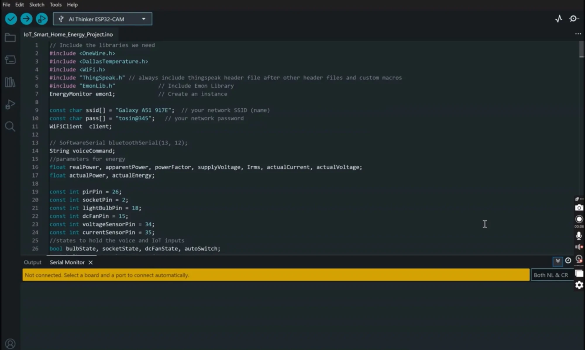
In programming the project design, we used the Arduino IDE for this purpose. We used some libraries for this program, and we declared which pin on the ESP32, the PIR motion sensor was connected to as well as other actuator input pins. We also stated some some Boolean variables to hold the states of the actuators like the lightbulb and socket. We wrote some custom functions in the program to take care of the things needed to be done. And since we were using thingspeak as our server, we needed to send sensor data to the Thingspeak platform on one channel and read the actuator states that is being command by the app buttons on another channel on Thingspeak. Lastly, we programmed the Bluetooth module to be able to convert Speech to text stings into specific commands that would change the states of the home model appliances in the design. Once we have coded all of these out, we can upload our code. Don’t worry, the Arduino code is free. Just check the link above, go to my GitHub repo to download the code free.
Mobile App with MIT App Inventor
The app was designed with MIT App Inventor, providing:
- Voice Control using Speech-to-Text.
- Buttons and switches for manual control.
- IoT integration with Thingspeak for remote monitoring.
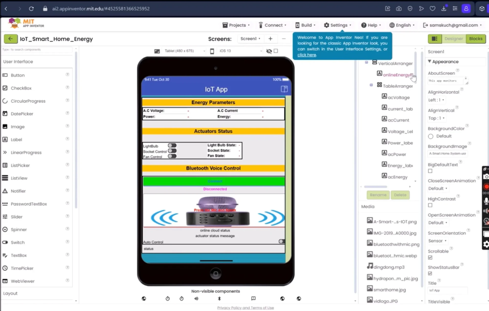
The next thing on the list is to program and design the app. This was done using the MIT appinventor. But if you are here and you want this app. Just comment below and I would send it to you FREE. We designed the app using the drag and drop widgets on the MIT appinventor platform, and once we were confortable with its design, we started with the code block side. And the included all the codes needed to work as expected. Also again, leave a comment and I will send you this app for free.
Thingspeak IoT Dashboard
We created two channels on Thingspeak:
- Data Channel: Sends voltage, current, and power readings from the ESP32 to Thingspeak, which the app fetches for display.
- Control Channel: Allows the app to send HIGH/LOW commands (1 or 0) to Thingspeak. The ESP32 reads this and actuates relays accordingly.
This setup allowed the project to work as both a monitoring and control system.
Voice Control Implementation
How Speech-to-Text Works in the App
When you press the mic button on the app and say “fan on”, the app converts your speech into text. Sometimes, due to accents or clarity, it may convert to “fan un”.
The app then sends this string over Bluetooth to the ESP32. The ESP32 checks the string using conditional statements and executes the command.
For example:
- “fan on” → relay for fan turns on.
- “light off” → relay for bulb switches off.
It’s simple, fast, and doesn’t require internet.
Energy Monitoring Explained
Measuring Voltage and Current
- The ZMPT101B measures the AC mains voltage.
- The 5A current sensor measures the current flowing through the load.
Calculating Power and Energy
- Power (W) = Voltage × Current.
- Energy (Wh) = Power × Time.
Instead of an RTC module, we used Arduino’s millis()/1000 function to keep track of time. This reduced hardware costs while still giving us accurate energy monitoring.
Answering Key Questions
How does the ESP32 connect with Thingspeak?
The ESP32 connects to WiFi and uses the Thingspeak API to send sensor data and fetch control values.
Can you control home appliances with Bluetooth voice commands?
Yes. The HC-05 Bluetooth module receives text commands from a voice-enabled mobile app and triggers relays connected to appliances.
What’s the best way to measure energy in a smart home project?
A combination of a voltage sensor (ZMPT101B) and a current sensor (ACS712 or 5A ring sensor) works well for accurate energy calculations.
Do I need an RTC module for energy monitoring?
Not always. You can use the Arduino millis() function to track elapsed time and calculate energy consumption.
What are the advantages of combining WiFi and Bluetooth in IoT projects?
WiFi provides cloud connectivity, while Bluetooth allows offline, low-latency control. Using both gives redundancy and flexibility.
Integrating All of It Together
IoT smart home monitoring with ESP32
This project is a perfect demonstration—one board, multiple features: Bluetooth, WiFi, IoT, and energy monitoring.
Best app platform for IoT smart homes
MIT App Inventor is beginner-friendly, but you can also upgrade to Flutter, React Native, or Android Studio for more advanced apps.
Thingspeak dashboard for smart home control
The dual-channel setup in Thingspeak makes it a lightweight yet powerful backend for real-time IoT systems.
Benefits of This Smart Home Project
- Voice control gives hands-free convenience.
- Dual Mode Function: As the project works on both automatic mode where it runs everything using its predefined set parameters
- Energy monitoring helps you understand and reduce power usage.
- IoT integration enables remote monitoring from anywhere.
- Low-cost setup compared to commercial smart home systems.
- Scalable—you can add more relays, sensors, or even automation rules.
Limitations and Challenges
- Voice recognition errors due to accent/speech variations.
- ESP32’s limited memory for Bluetooth tasks.
- Power calibration needed for accuracy.
- Relays are electromechanical and can wear out over time.
Future Improvements
- Use ESP32’s internal Bluetooth with memory optimization.
- Add temperature and motion sensors for automation.
- Upgrade to solar-powered operation for sustainability.
- Implement AI-based voice recognition for better accuracy.
- Replace Thingspeak with MQTT + Node-RED for more control.
Conclusion – A Step Toward the Future
This project shows how affordable hardware and DIY ingenuity can bring the concept of smart homes to life. By combining ESP32, relays, sensors, Bluetooth, and IoT dashboards, we created a model that not only controls appliances but also tracks energy use.
And the best part? You don’t need to be an engineer to build it. With some patience, creativity, and the right tools, you can make your home smarter—one relay at a time.
FAQs
Can this system work without internet?
Yes, the Bluetooth voice control works without internet. But the IoT features need WiFi.
Can I expand the system to more appliances?
Definitely. Just add more relays and update the code.
How accurate is the energy monitoring?
With calibration, you can achieve good accuracy, usually within ±5%.
Is the MIT App Inventor app customizable?
Yes, you can add more buttons, labels, or even redesign the interface.
Can I use this project in a real house?
Yes, but ensure proper insulation, safety relays, and certified electrical enclosures for real AC mains.

