
Introduction
Imagine being able to switch off your lights, monitor your room, or get notified about smoke hazards right from your phone. Sounds futuristic? Not anymore. With just a few affordable components and a bit of DIY spirit, you can build your own IoT home automation and surveillance system using Arduino, ESP32-Cam, and the Blynk app. In this post, I’ll walk you through a real-life project I built that combines smart control and surveillance into one powerful setup.
Whether you’re a curious tinkerer or someone looking for practical home automation, you’re going to love this guide.
Required Hardware & Tools
Before we dive into the connections and code, let’s quickly run through what you’ll need:
Components:
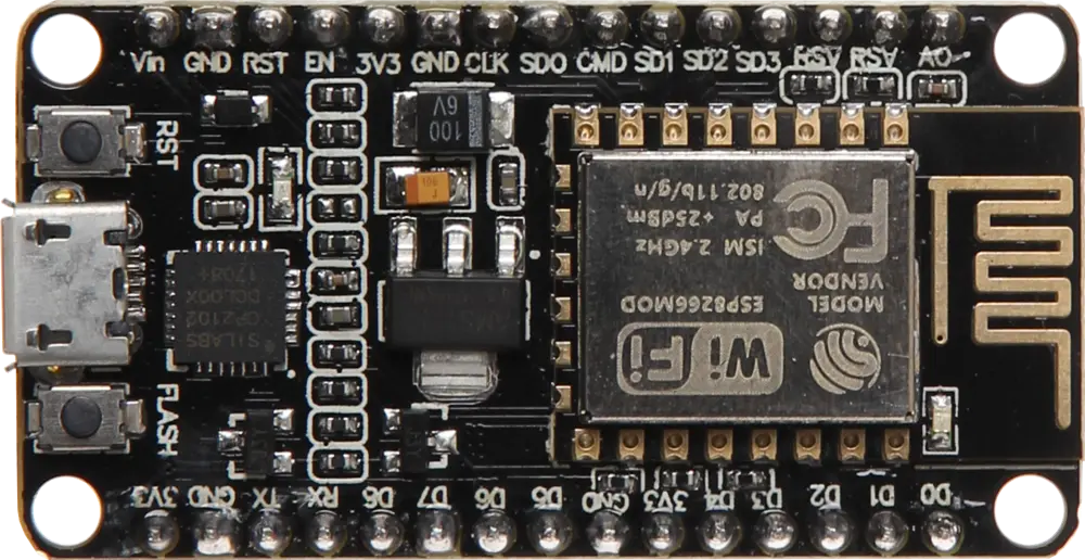
- 1x NodeMCU (ESP8266 development board)
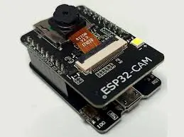
- 1x ESP32-Cam module
- 1x DC Fan
- 1x TIP41C NPN transistor
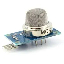
- 1x Smoke sensor module (MQ-2 or MQ-135)
- 2x Single-channel solid state relay module
- 1x Light bulb (A.C powered)
- 1x Socket or extension switch
- 4x JST connection wires
- Veroboard
- Power supply (5V DC regulated)
Software:
- Arduino IDE
- Blynk Legacy App (or Blynk IoT)
- Google Cloud Platform (for streaming server)
- Node.js (for web socket setup)
Circuit Wiring & Connections
Explanation of The Schematic Diagram
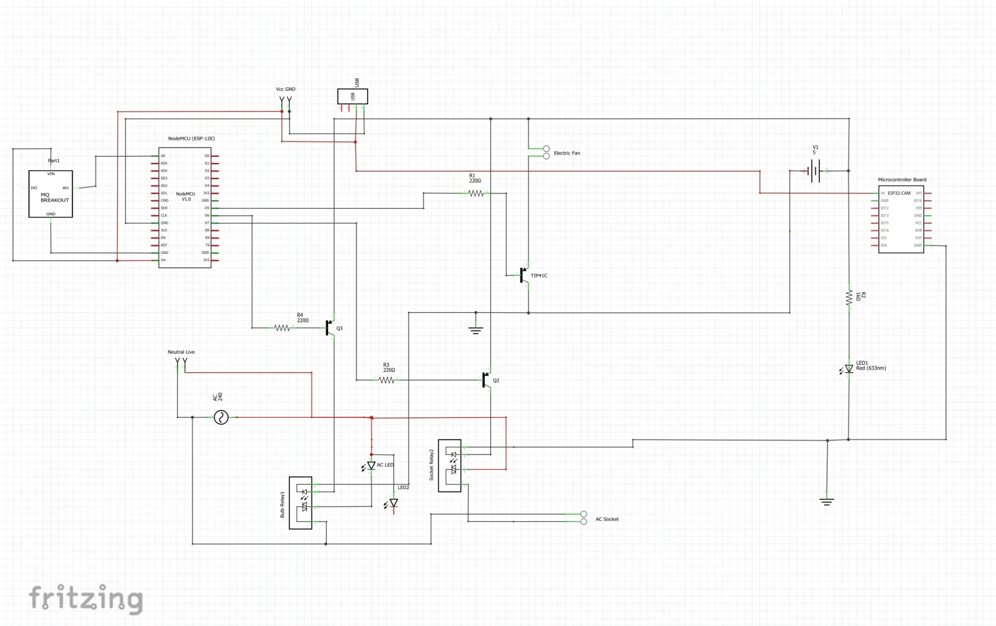
The schematic diagram shown above used both the NodeMCU (ESP8266-12E) and the ESP32 Cam development boards to accomplish the tasks of the project. The ESP32 Cam was connected only to the 5V DC power rails. We used this to only stream online video feeds. This is because, we didn’t wants an IO pin connections to any sensor or actuators to interrupt the real time video streaming.
Let’s break down how the system is wired:
NodeMCU:
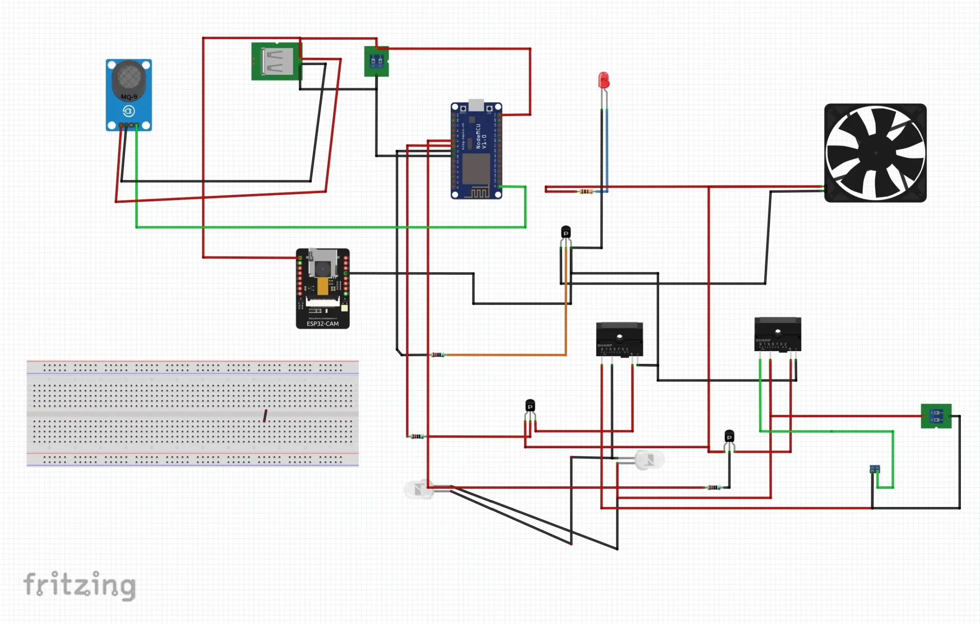
The pictorial or breadboard view of the schematic diagram shown above shows a separate connection of the relay modules using transistor and single solid state relays for them. In reality, the single channel solid state relay comes as a module and you just do your connection with ease.
As of the time when this schematic diagram was drawn on Fritzing, there was no single part of module representation for the single channel solid state relay. The summary of the connection can be stated as:
- Relay Module 1: Connected to D6 (controls A.C light). This was used to turn or or off the light-bulb from the Blynk app at will by the user. Since the D6 pinout of the NodeMCU output a logic voltage of 3.3V, the relay module itself used a logic “ON” stage of 3.3V and 0V for “OFF” hence why we chose it.
- Relay Module 2: Connected to D7 (controls A.C socket). As the first relay module was connected, we also followed the same procedures but this time the input pin of the relay module was connected to the D7 pin on the NodeMCU.
- Smoke Sensor: Connected to A0 (analog input). Since this module itself has an analog output. The only analog pinout on the NodeMCU was the A0 pin and we connect the analog output pin of the smoke sensor to this pin.
- DC Fan: The DC fan was controlled via PWM on D5 through the TIP41C transistor in common emitter configuration
ESP32-Cam:
- Powered through a regulated 5V line
- Connected to USB-Serial adapter for programming (TX-RX cross, GND-GND)
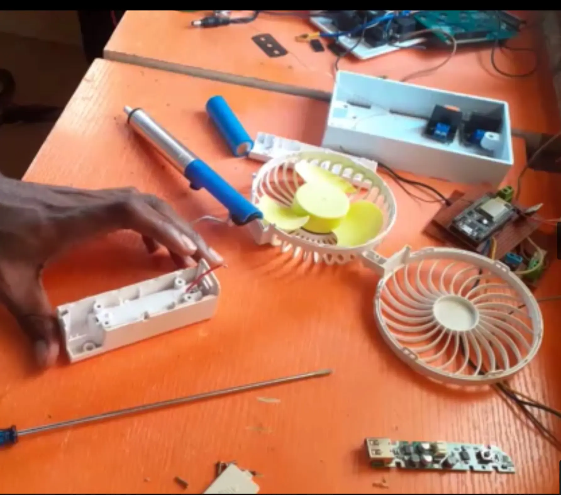
Tip: Make sure the grounds of all modules are connected together. Power the relay modules separately if you’re experiencing reboot issues. Also, the DC fan was disassembled as shown in the image above. We needed only the DC motor and the fan blades connected to it. So we disassembled DC hand fan and used the only needed parts inside.
Code & Blynk App Setup
Let’s now bring our project to life. This would mean that we need to set up the Blynk dashboard. It is very important to note that the Blynk version used to develop this project was the Blynk legacy. That version has long been discontinued. That said, the project can still work on the new Blynk IoT version.
Setting Up the Blynk App:
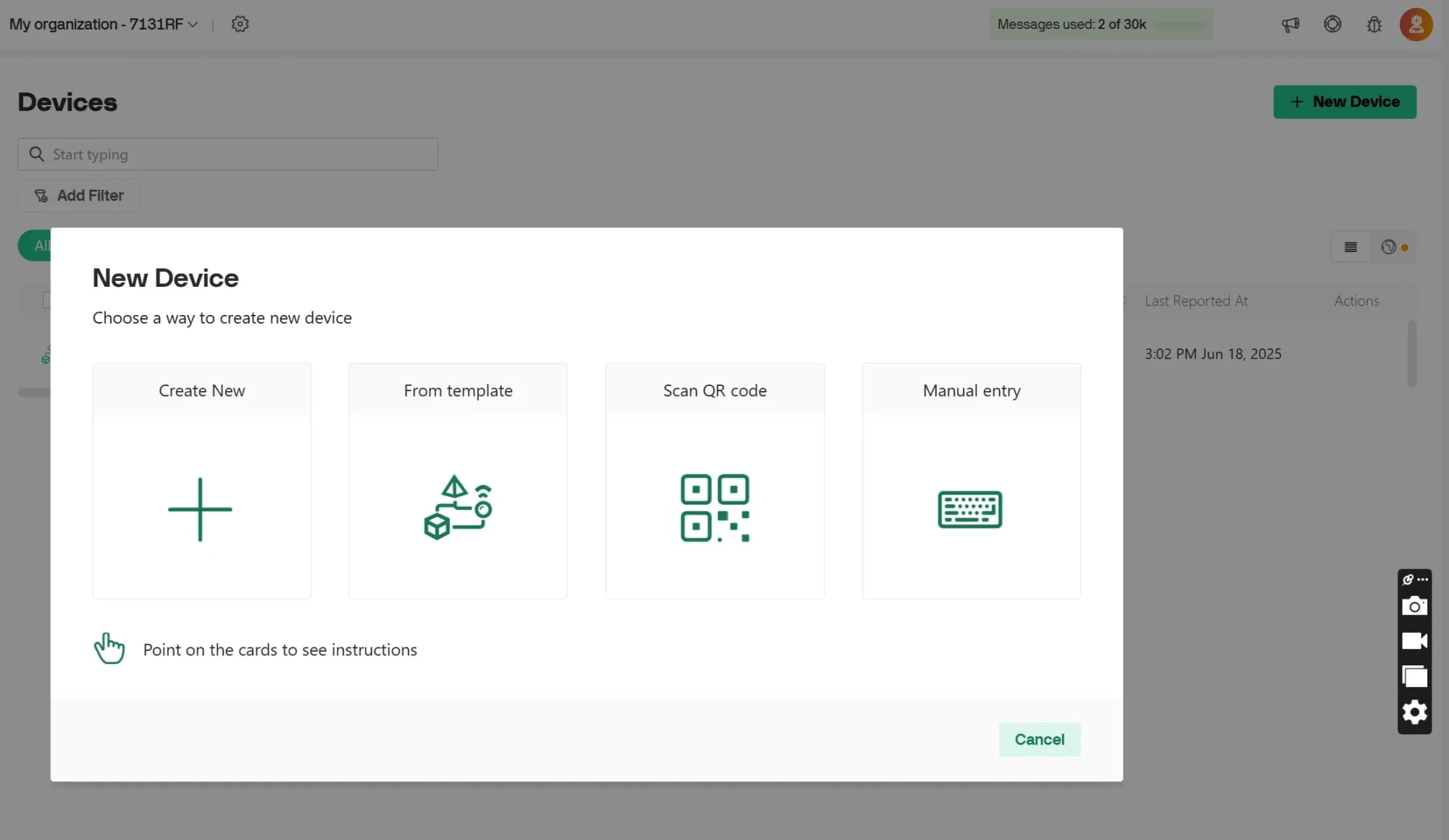
- Download Blynk App: You can follow the link here to down the Blynk app. Of course, you would have to first signup if you haven’t yet. For the Blynk IoT, you would have to set up the project. By adding a New Device, Create New, etc. Read this IoT Based Gas Leak Detection Project to know how to do this.
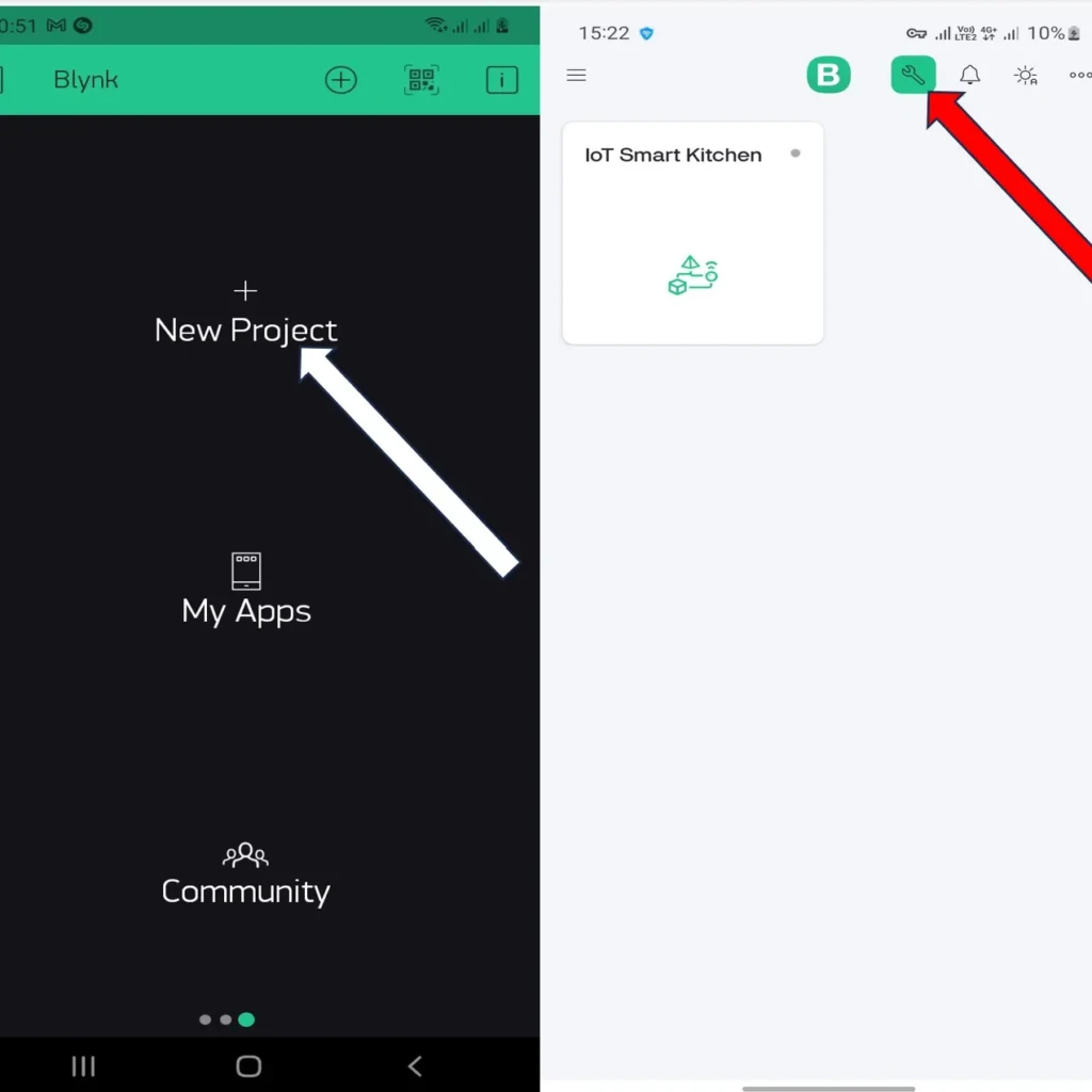
Using the Blynk Legacy version, you have to select “New Project” on the Mobile App. But using the Blynk IoT version. Click on the “+” button next and you need to click on the settings icon and follow the steps below next.
- Create a new project and choose NodeMCU or ESP8266 as the device.
- Add widgets: buttons for relays, gauge for smoke sensor, and video widget
- Copy your Auth Token and save it for the Arduino sketch.
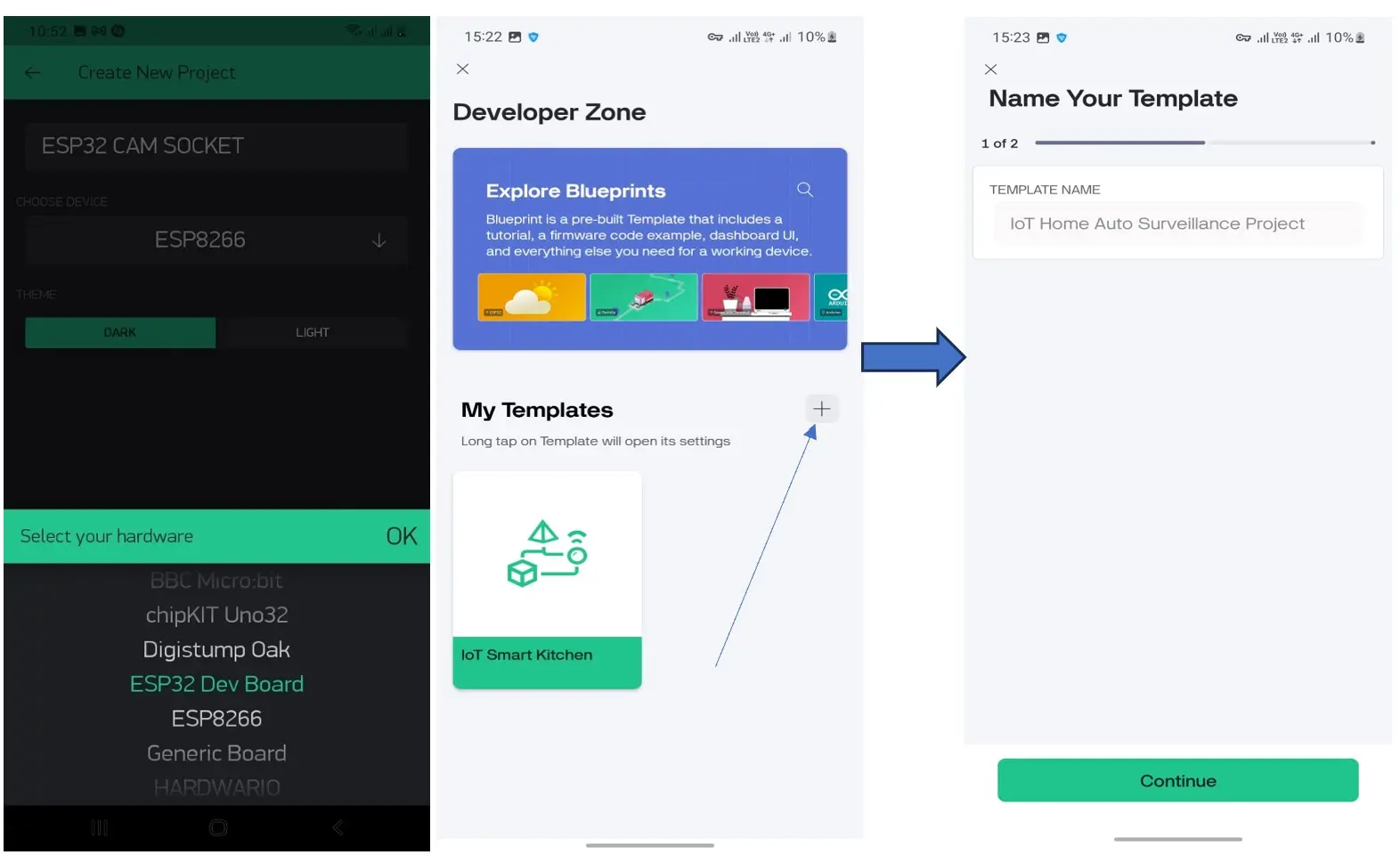
On the Blynk Legacy, you can name your project, select the Device you are running the project under the input box where the title is. Using the Blynk IoT version, you would have to input the title of project in the “Template Name” input box. After which you can click “continue” below.
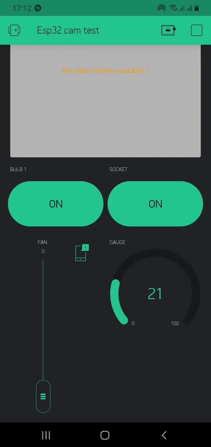
We needed the two button switched; one to control the light bulb and this was labelled “Bulb” and the other one is to control the socket. This was labelled “Socket”. The vertical slider labelled “Fan” was used to send PWM pulses to the GPIO on the NodeMCU and we used the gauge widget to show the percentage of the smoke reading concentration within the vicinity. And we added a notifier widget in between that would trigger in-app alerts.
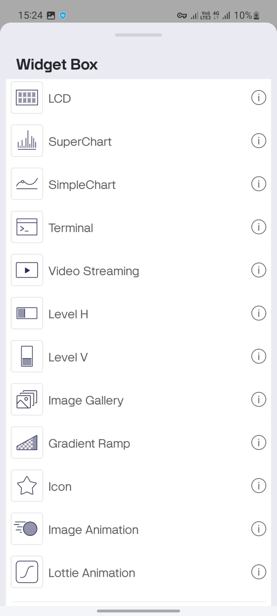
The same also goes for using the Blynk 2.0; you can pick and align the widgets from the list of widgets in the widget box dropdown menu. The video streaming widget is free so you don’t have to worry about paying.
Programing the Project Design: Arduino Sketch Overview
- The NodeMCU reads smoke levels from the analog pin
- The NodeMCU controls relays and fan using digital and PWM pins
- Sends smoke data and receives commands via Blynk
- Sends notification when smoke level crosses threshold
- The ESP32 Cam video is streamed on the video streaming widget on the Blynk app.
During the programing of the project design using Arduino IDE, we programmed both development boards separately. The ESP32 Cam was programmed using its own programming board whereas the NodeMCU was programmed as it is.
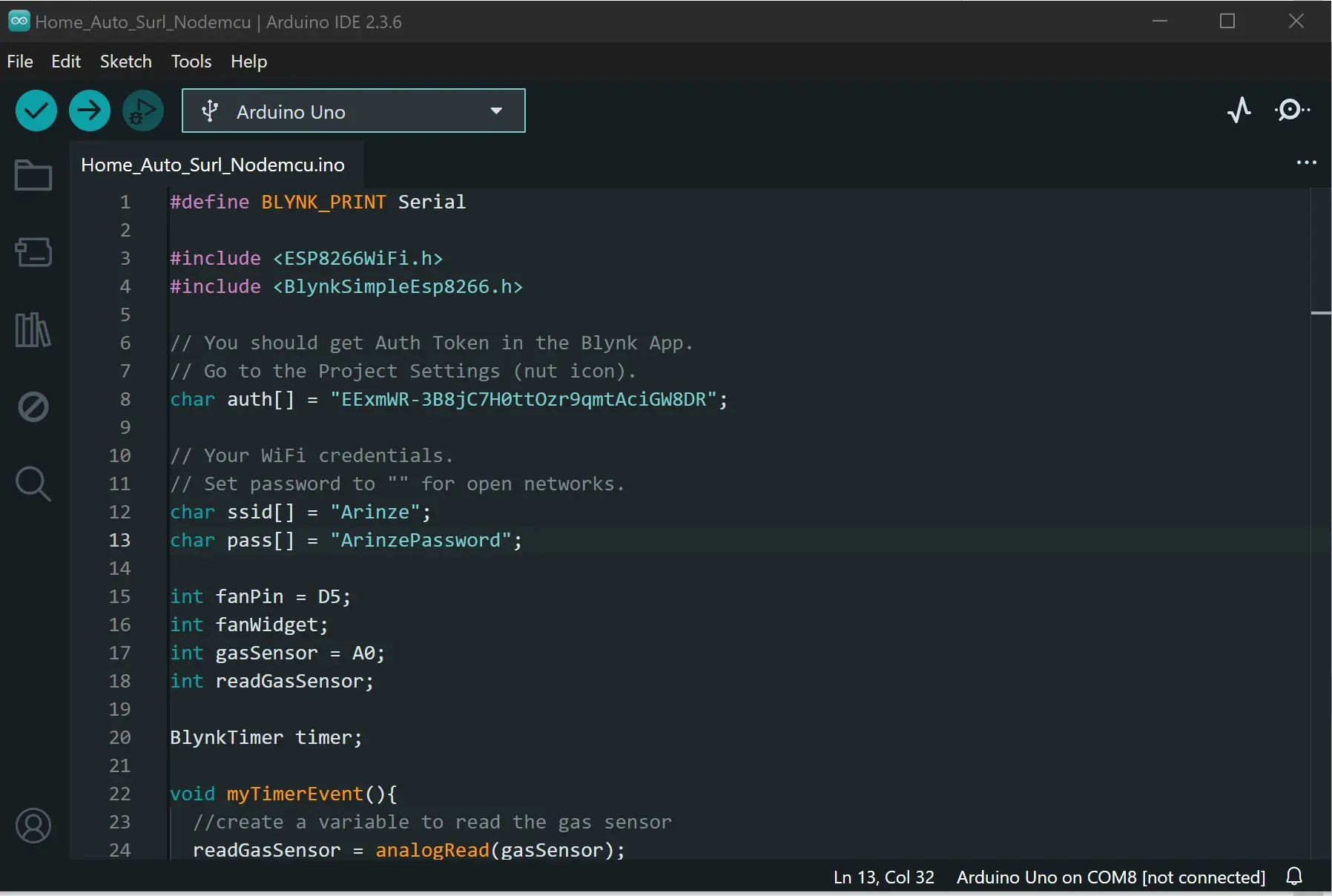
Arduino Code for NodeMCU:
#define BLYNK_PRINT Serial
#include <ESP8266WiFi.h>
#include <BlynkSimpleEsp8266.h>
// You should get Auth Token in the Blynk App.
// Go to the Project Settings (nut icon).
char auth[] = "EExmWR-3B8jC7H0ttOzr9qmtAciGW8DR";
// Your WiFi credentials.
// Set password to "" for open networks.
char ssid[] = "Arinze";
char pass[] = "ArinzePassword";
int fanPin = D5;
int fanWidget;
int gasSensor = A0;
int readGasSensor;
BlynkTimer timer;
void myTimerEvent(){
//create a variable to read the gas sensor
readGasSensor = analogRead(gasSensor);
//first map the readings to 100% max.
readGasSensor = map(readGasSensor, 0, 1023, 0, 100);
//push it to the widget on blynk app
Blynk.virtualWrite(V5, readGasSensor);
//use control flow to check when to send an alert
if(readGasSensor >= 60){
Blynk.notify("THERE IS SMOKE SENSED, CHECK FOR FIRE");
}
else{
}
}
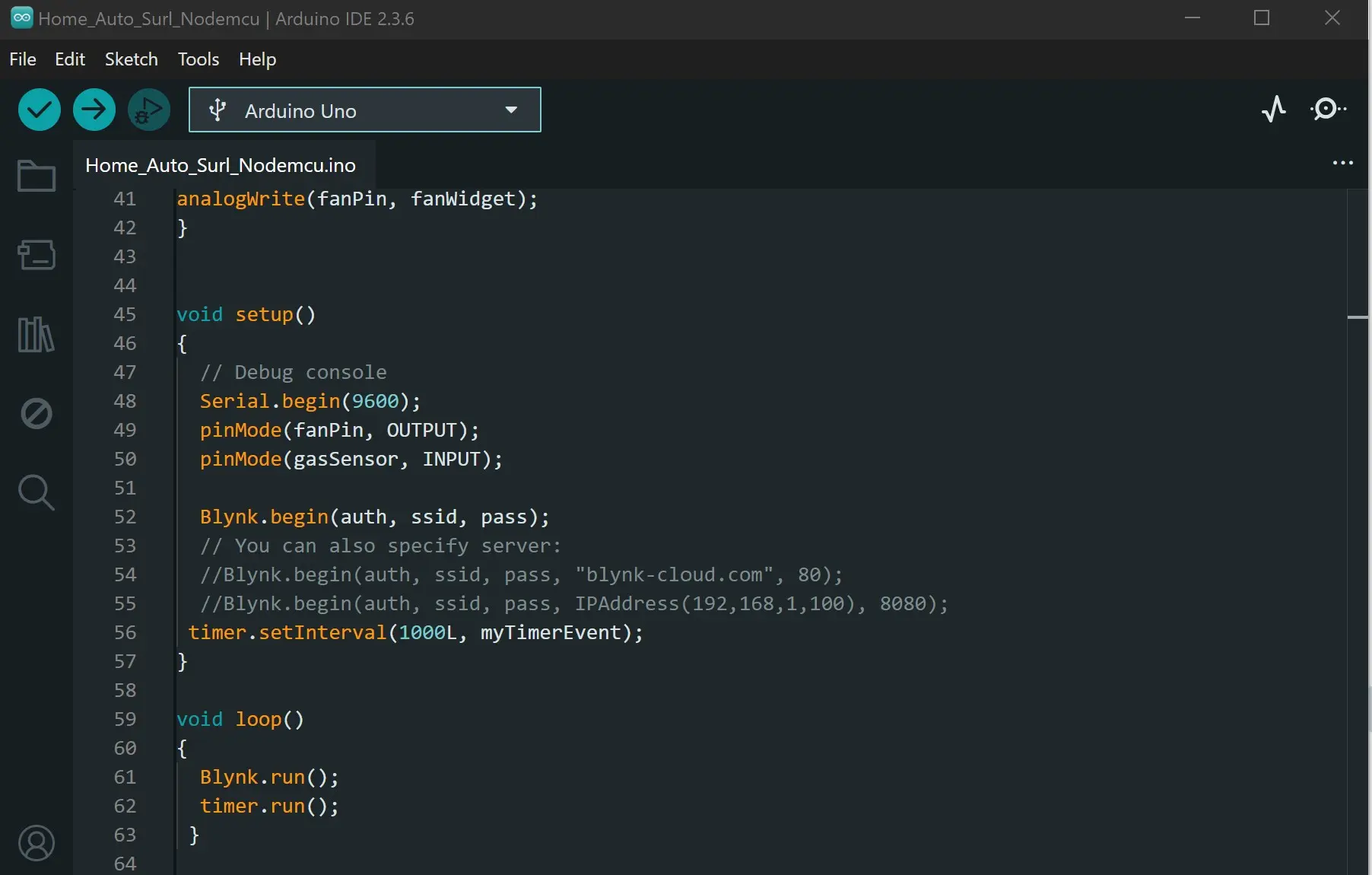
BLYNK_WRITE(V1) {
fanWidget = param.asInt();
analogWrite(fanPin, fanWidget);
}
void setup()
{
// Debug console
Serial.begin(9600);
pinMode(fanPin, OUTPUT);
pinMode(gasSensor, INPUT);
Blynk.begin(auth, ssid, pass);
// You can also specify server:
//Blynk.begin(auth, ssid, pass, "blynk-cloud.com", 80);
//Blynk.begin(auth, ssid, pass, IPAddress(192,168,1,100), 8080);
timer.setInterval(1000L, myTimerEvent);
}
void loop()
{
Blynk.run();
timer.run();
}
Explanation of the NodeMCU Arduino Code
The Arduino code above is pretty simple; this Arduino code is designed to create a simple home safety and automation system using an ESP8266 board and the Blynk platform. At its core, the program connects the ESP8266 to a Wi-Fi network and a Blynk project. By defining Blynk’s authentication token (auth) and the Wi-Fi credentials (ssid and pass), the code establishes a connection that allows the microcontroller to communicate with the Blynk app on a smartphone. This connection is the foundation for both monitoring a gas sensor and controlling a fan, enabling remote interaction with the physical hardware.
The code features two primary functions: a BlynkTimer event for sensor monitoring and a Blynk write handler for remote fan control. The myTimerEvent function runs every second and reads data from a gas sensor connected to pin A0. It then converts the raw sensor data (from 0-1023) into a percentage (0-100) using the map() function. This converted value is sent to a virtual pin V5 in the Blynk app, allowing a user to see the gas level in real-time. Additionally, the code includes a safety feature: if the gas reading exceeds 60%, it automatically sends a push notification to the user’s phone with a warning message, acting as a simple gas and smoke alarm.
The fan control functionality is handled by the BLYNK_WRITE(V1) block. This specific function is a Blynk handler that listens for changes from a widget (like a slider) attached to virtual pin V1 in the Blynk app. When a user adjusts this widget, its value is sent to the ESP8266, stored in the fanWidget variable, and then used to set the speed of a fan connected to digital pin D5. This allows a user to remotely turn the fan on or off, or even control its speed, all from their phone. The setup() function initializes the necessary hardware pins and establishes the Blynk connection, while the loop() continuously checks for new Blynk and timer events to ensure everything runs smoothly.
Live Streaming Feature
One of the coolest parts of this project is the video stream. To make the project on a localhost, you can just use the ESP32 Cam video stream. But to truly make it stream over IoT using Google Cloud Virtual Machines (VM), you would need to used node.JS and since npm comes bundled with Node.js, npm would install Express into a folder of your choice if you want.
Step 1: Install Node.js (which includes npm)
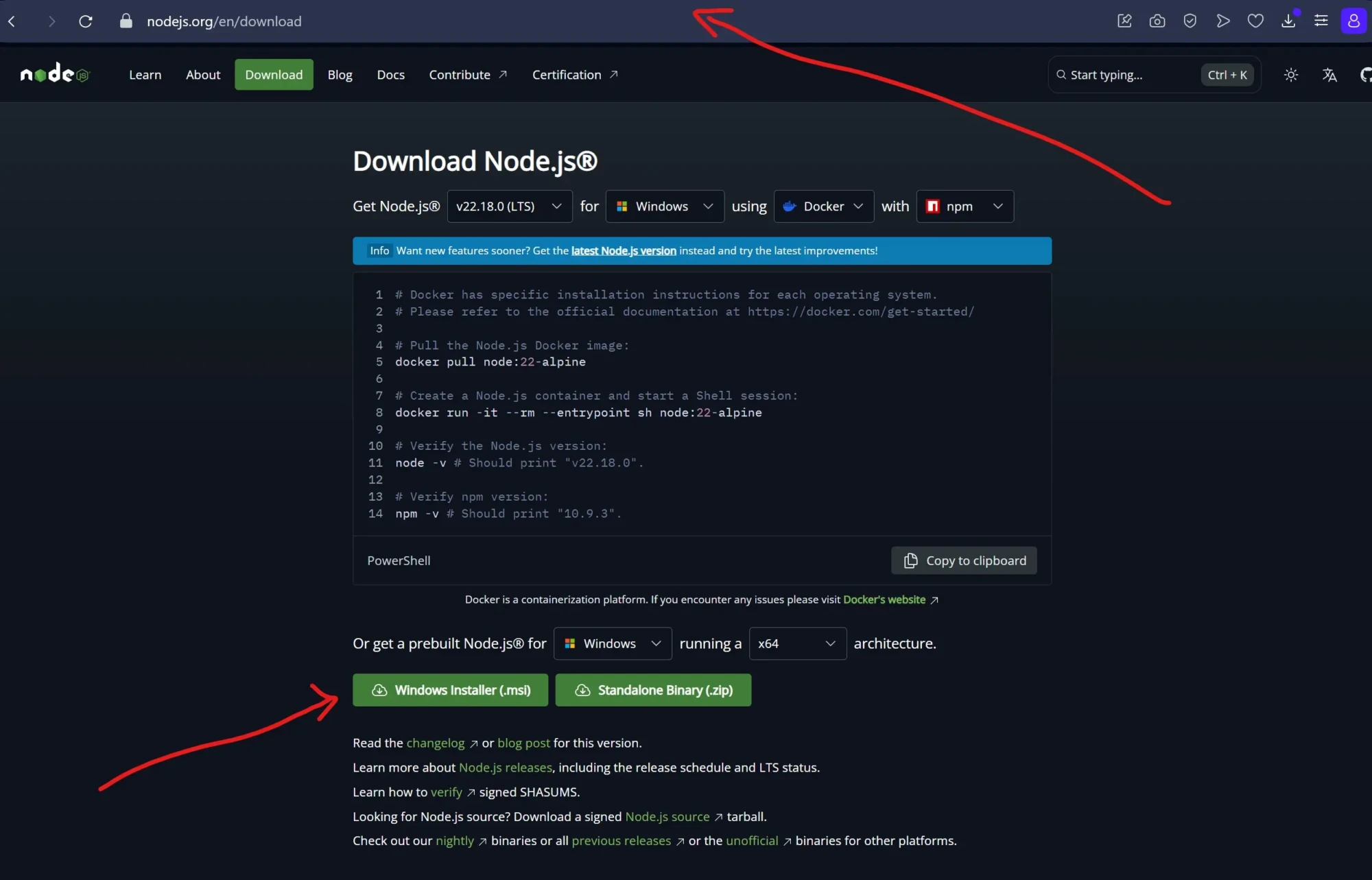
Download the node.JS from its official website and proceed to installing the Windows installer file (.msi) as shown above. IF you are using other OS, there should be option for you to do this also.
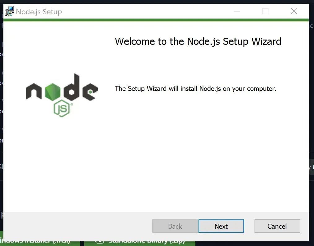
Next, after the successful download, open the .exe file and click on install. Accept the license agreement and click “next” until you can be able to successfully install the node.js onto your PC. You can also choose to specify which folder you want the installation to take place too.
Step 2: Creating the Web Socket Using Command Prompt
Upon successful installation, you are ready then to move to the next level which is testing if the node.JS and npm was installed successfully. To do this, open your command prompt as an admin. Type “cmd” in your state menu and select open as an administrator.
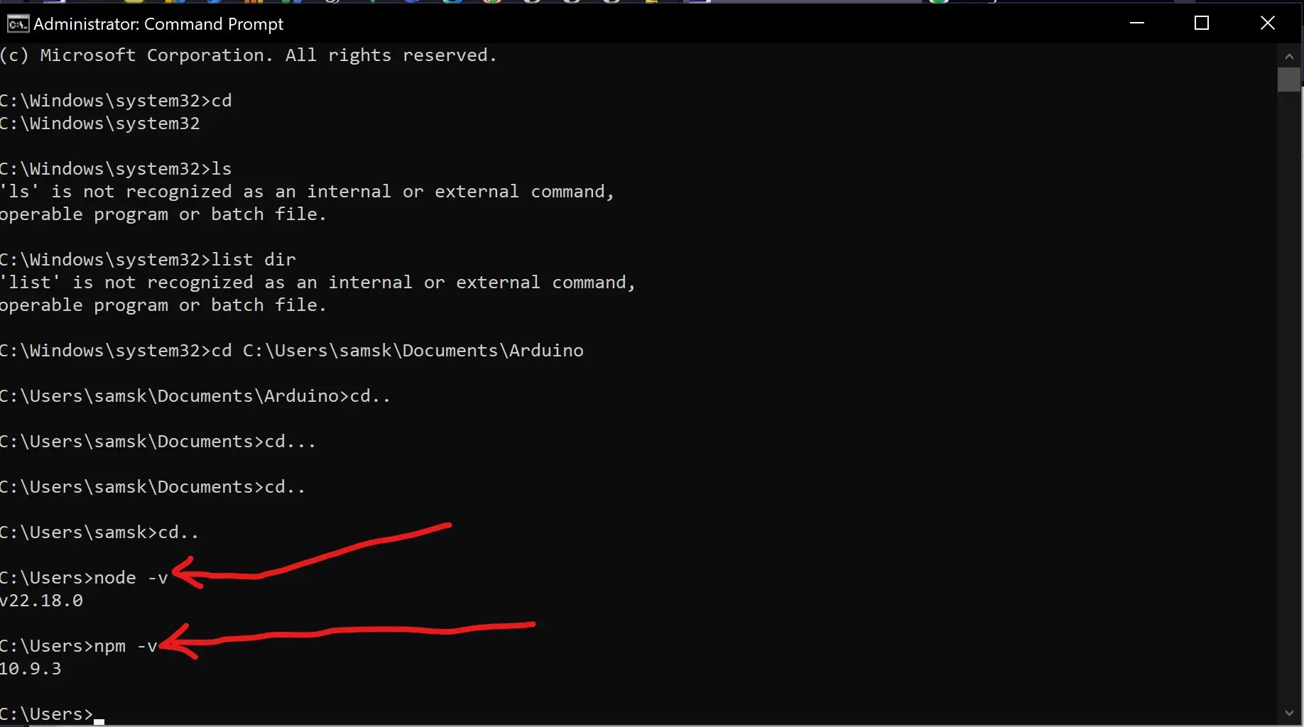
After this is opened, type the following command:
node -v
npm -v
The above following syntax would prompt your PC to show the node.js version installed on the PC and the npm version too.
We would proceed to create a folder next. For us here, we created our own web socket folder inside the Arduino folder and name it ESP32 Cam Web Socket. Select this folder from your Command prompt by type the command “cd yourFolderPath”.
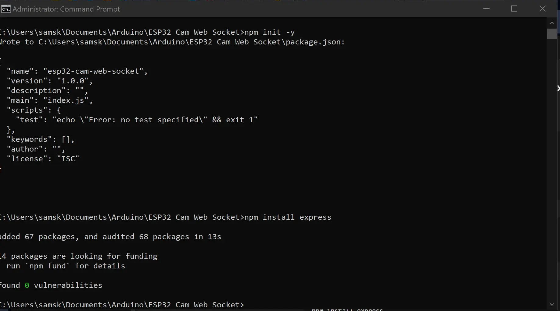
In this selected folder we can install the express locally on this folder. By typing first: npm init -y
After it has finished executing that, you can type the command next:
npm install express
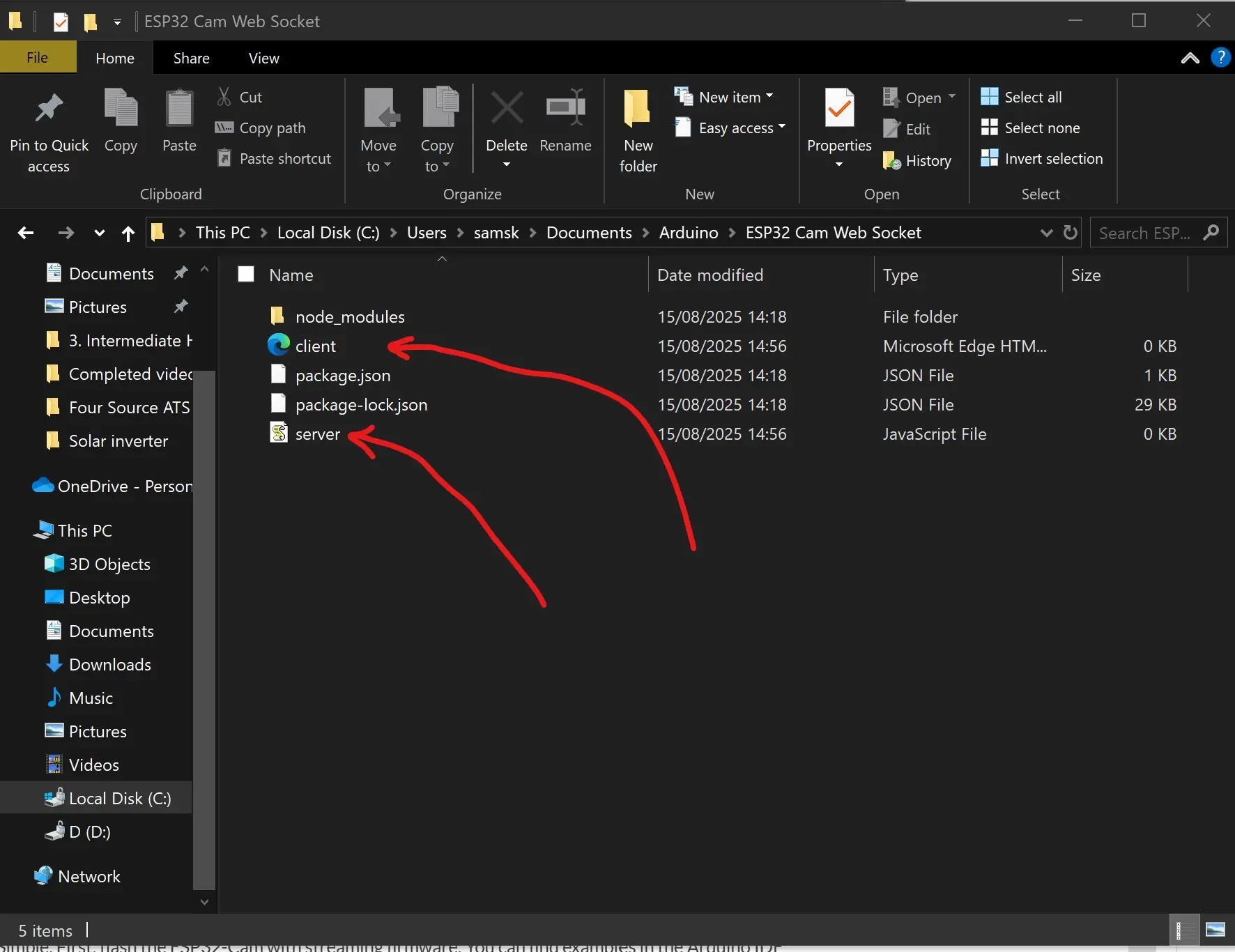
And that is it for that. Next is to create two important files: the server.js file and client.html file. We can either use the simpler way of creating this file using a simple text editor like notepad; dragging and dropping it into the folder itself or just creating it directory using the cmd. I used the shortcut of creating the files using the cmd option. By simply typing the syntax:
type nul > server.js
type nul > client.html
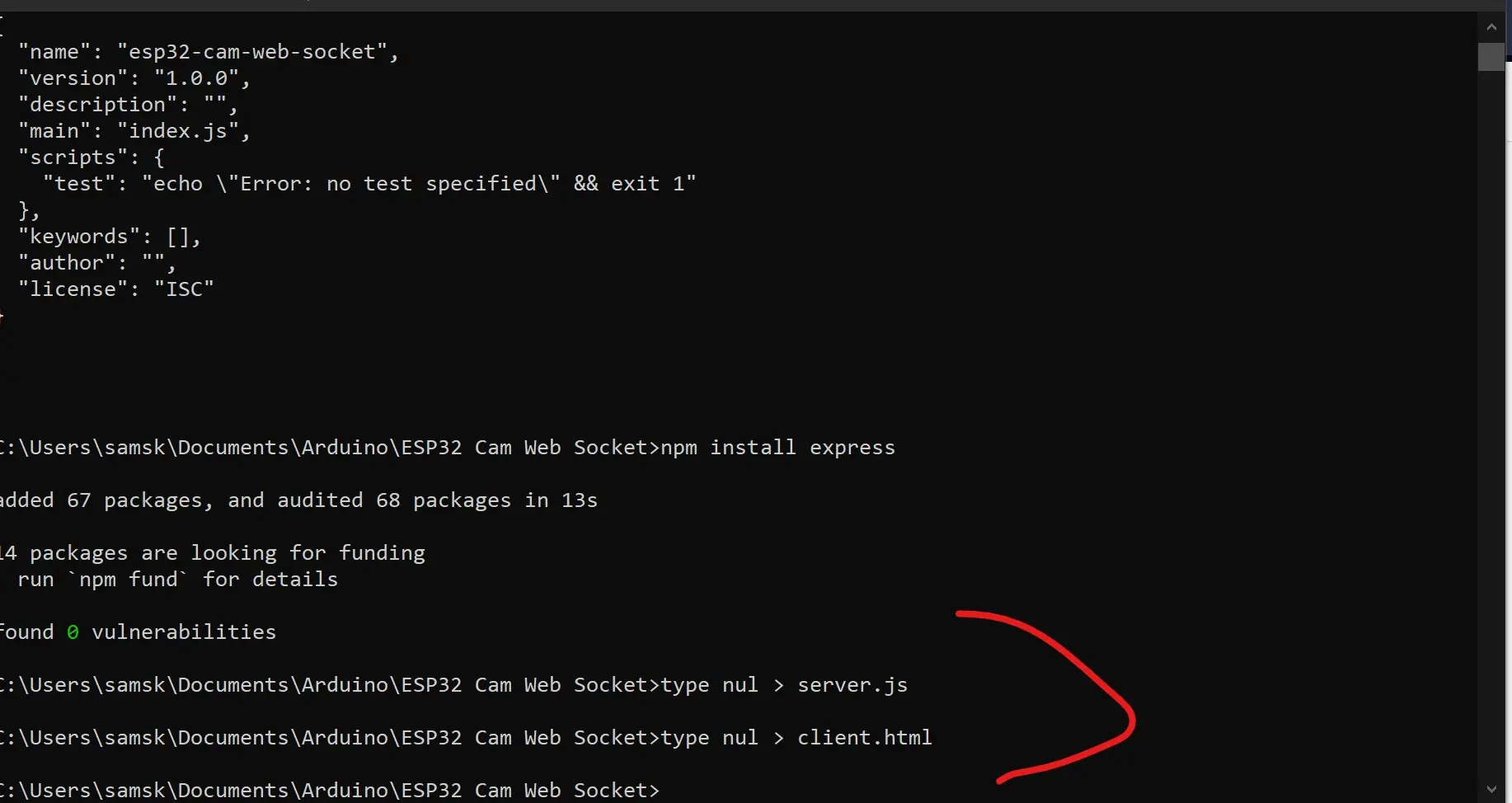
These created the two files that I needed to proceed next in the following phase of the project design. The next phase would be to open these two files using VSCode editor or any other text editor of your preference. We would need to put in some code in them to make sure they work.
javascript code for the server.js file
const path = require('path');
const express = require('express');
const WebSocket = require('ws');
const app = express();

const WS_PORT  = xxxx; // WebSocket server port
const HTTP_PORT = xxx; // HTTP server port

const wsServer = new WebSocket.Server({port: WS_PORT}, ()=> console.log(`WS Server is listening at ${WS_PORT}`));

let connectedClients = [];
wsServer.on('connection', (ws, req)=>{
    console.log('Connected');
    connectedClients.push(ws);

    ws.on('message', data => {
        connectedClients.forEach((ws,i)=>{
            if(ws.readyState === ws.OPEN){
                ws.send(data);
            }else{
                connectedClients.splice(i ,1);
            }
        })
    });
});

app.get('/client',(req,res)=>res.sendFile(path.resolve(__dirname, './client.html')));
app.listen(HTTP_PORT, ()=> console.log(`HTTP server listening at ${HTTP_PORT}`));
HTML Code for the Client Side
<html>
    <head>
        <title>Client</title>
    </head>
    <body>
        <img src="">
        <script>
            const img = document.querySelector('img');
            const WS_URL = 'ws:///10.146.182.101:8888';
            const ws = new WebSocket(WS_URL);
            let urlObject;
            ws.onopen = () => console.log(`Connected to ${WS_URL}`);
            ws.onmessage = message => {
                const arrayBuffer = message.data;
                if(urlObject){
                    URL.revokeObjectURL(urlObject);
                }
                urlObject = URL.createObjectURL(new Blob([arrayBuffer]));
                img.src = urlObject;
            }
        </script>
    </body>
</html>
For the ws_URL, the IP address would have to be the IP address of your PC. preferably a static IP address. Add the port of that as define in the server.js file.
Open the Arduino file, you can download all the local host file from this GitHub file here. You can select the type of ESP32 Cam board that you are using and upload the code. Wait for it to successfully upload. Once this is done, you should open the serial monitor. And after a while, you will see it saying it is connected to the webserver. Copy the IP address on the serial monitor and paste it into any web browser tab and hit the enter key. And you can stream the video on the local host. This is ONLY POSSIBLE PROVIDED THE DEVICE WITH THE BROWSER IS CONNECTED TO THE WiFi NETWORK.
How to Stream The Video Over the Internet Using Google Cloud Platform (GCP)
login into your GCP account and go to compute engine.
Select Virtual Machine Instance
Click create and name the VM instance and use only lowercase letters
Choose the location nearest to you (region)
Choose a zone too.
Since the server is for pushing small images from the esp32 cam client to other clients, we chose g1-small
Under machine type, you can choose 1.7Gb memory
under server choose Ubuntu 18.04 LTS
Leave the rest as it is,
Under firewall, check all the checkboxes
select create after all of these are done.
After that, connect the VM instance via SSH. And when this was connected, we can install the Node.js on this virtual machine.
Create the project directory by typing “mkdir nodeServer”.
Then go into that directory using the command “cd nodeSever”
Once there you can list the files and directories there using the command “ls”
use the command, curl -sL https://deb.nodesource.com/setup_10.x | sudo -E bash –
Install node.js by typing ‘sudo apt install nodejs’ and key in “Y” when prompted to continue or not.
You can check your node.js version or npm version after this. by typing node –version and npm –version
As shown before, create two files; the client.html and the server.js file. Then use the Vi editor to open the server.js file. Just basically copy and past the code from the file below and change the port for http 80. GCP has has web socket port which is 65080. close the VI editor and save the code by typing “:q!”
Creating Firewall Rules
Next set up the firewall. and set the wirewall rules. Also use the VI editor to open the client.html file. copy and paste the code inside. Copy the external IP address from the VM instance and put in the code. put the port of the GCP and as shown in the local host code. THis would become your websocket address. save your file and exit. Then run the server.js by typing “sudo node server.js”
How Do I Build a Surveillance Camera Using ESP32‑Cam and Blynk?
Simple. First, flash the ESP32-Cam with streaming firmware. You can find examples in the Arduino IDE under ESP32 -> Camera -> CameraWebServer. Once that works:
- Use Node.js to create a web socket that captures and relays the video
- Host the stream on a Google Cloud VM
- Place the video stream link inside the Blynk video widget
Setting Up The Arduino Hardware Part
You will need to disassemble the DC as pictured above and use the useful part of it.
Once the DC hand fan has been disassembled, we can proceed to measure the voltage of the DC fan. The idea is to find out what is the maximum voltage that is powering the DC fan at its maximum speed. Once we are able to find out this voltage; we can be able to reverse engineer it using the control Widget from Blynk dashboard and also using the t.i.p.41C NPN transistor configuration. Using the multimeter instrument, and its reading set to the DC voltage measurement reading, we can see that the voltage of the DC fan when we crank up the speed by pressing the speed button 3 times. The measured voltage is displayed as 7.89 volts. We can set the supply voltage from the collector to range from 0 volts to 9 Volts.
The USB soldering Iron works for us because we can just plug it into our PC USB port and use it to solder whatever we want to solder. However, the soldering iron itself came with its own solder. This is more flexible and softer to touch and it easily melt under the heat of the soldering Iron. The USB soldering iron has its own temperature regulation and we used the highest temperature for this job.
Smoke Detection and Alerts
Here’s where things get serious—safety first.
How to Get Notifications with Images from ESP32‑Cam Using Blynk?
Currently, Blynk doesn’t directly support image upload. But there’s a workaround:
- Set ESP32-Cam to take a snapshot when smoke level exceeds 700 (or any value you choose)
- Store it temporarily on the web socket server
- Send notification with a clickable link to that image
Meanwhile, NodeMCU is already triggering Blynk alerts when smoke levels are high.
ESP32 Cam Motion Detection PIR Blynk Integration
Want to spice up your system with motion detection?
Add a PIR sensor to the ESP32-Cam. Modify the CameraWebServer code to start video or take a picture when motion is detected. Combine that with a notification using the Blynk HTTP API.
ESP32 Cam Surveillance System Arduino Blynk
This combo is powerful:
- ESP32-Cam for vision
- NodeMCU for actuator control and sensing
- Blynk app for a unified control dashboard
Together, they form a complete DIY surveillance system.
Testing & Troubleshooting Tips
Here are some roadblocks you may encounter:
- ESP32-Cam Brownout: Use external 5V 2A supply
- Camera Init Failed: Check GPIO pins and camera model selection
- Relays Flickering: Separate power supplies
- No Stream in Blynk: Check that your video link is HTTP (not HTTPS)
Can Blynk Support Video Streaming from ESP32‑Cam?
Yes, indirectly. Blynk’s video widget accepts HTTP streams. You’ll need to set up a web socket on a cloud server (like GCP or AWS) to serve the ESP32-Cam feed.
Arduino ESP32 Cam Doorbell Security with Blynk
Thinking ahead? You can build a smart doorbell system:
- ESP32-Cam detects someone at the door (with PIR or push button)
- Takes a picture or starts streaming
- Sends notification to your phone via Blynk
This can be a standalone future project too.
Is ESP32‑Cam Secure for Home Surveillance Projects?
It depends. ESP32-Cam doesn’t have built-in encryption. For sensitive surveillance:
- Use strong Wi-Fi passwords
- Restrict access to stream URL
- Use VPN or secure tunnels like ngrok if exposing ports
Enhancements & Future Extensions
Here are some ideas to take things up a notch:
- Face Recognition using ESP-WHO library
- Node-RED Integration for automation workflows
- Home Assistant Compatibility via MQTT
- Sound Sensor to detect unusual sounds
- Cloud Data Logging using Firebase or Thingspeak
Conclusion
That’s a wrap! With just an ESP32-Cam, NodeMCU, and Blynk, you’ve got a mini smart home setup right in your hands. You now control lights and sockets, monitor air quality, and stream live video—all from a single app.
Don’t stop here. Tinker more, improve security, maybe add facial recognition or integrate with Alexa or Google Home. The possibilities are endless!
FAQs
1. Can I use Blynk with ESP32-Cam only, without NodeMCU?
Yes, but you’ll need to modify the code to support Blynk library with ESP32. NodeMCU is used here to offload actuator control.
2. Why does my ESP32-Cam keep rebooting?
Likely a power issue. Use a stable 5V, 2A supply and ensure GPIO0 is correctly set during flashing.
3. How can I make my stream private?
Run it on a password-protected web server or use a VPN. Avoid exposing ports directly.
4. Can I log smoke data somewhere?
Yes! Integrate Firebase or Thingspeak in your NodeMCU code to log sensor values over time.
5. Will this work on Blynk 2.0 (Blynk IoT)?
Yes, with slight adjustments in widget settings and authentication. The basic logic remains the same.

