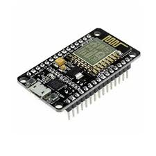
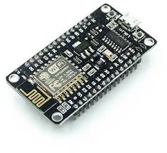
- Frequency Range: 2.412 – 2.484 GHz
- Serial Transmission: 110 – 921600 bps, TCP Client 5
- SDIO 2.0, SPI and UART Interface available
- PWM available
- One ADC channel available
- Programmable GPIO available
- Wireless Network Type: STA / AP / STA + AP
- Security Type: WEP / WPA-PSK / WPA2-PSK
- Encryption Type: WEP64 / WEP128 / TKIP / AES
- Network Protocol: IPv4, TCP / UDP / FTP / HTTP
- Operating Voltage: 3.3V
- Maximum current allowed to draw per pin: 15mA
- Power down leakage current of < 10uA
- Integrated low power 32-bit MCU
- Onboard PCB Antenna
- Wake up and transmit packets in < 2ms
- Standby power consumption of < 1.0mW
- Operating Temperature: -40ºC to +125 ºC
| Pin | Name | Description |
| 1 | RST | Reset Pin of the module |
| 2 | ADC | Analog Input Pin for 10-bit ADC (0V to1V) |
| 3 | EN | Module Enable Pin (Active HIGH) |
| 4 | GPIO16 | General Purpose Input Output Pin 16 |
| 5 | GPIO14 | General Purpose Input Output Pin 14 |
| 6 | GPIO12 | General Purpose Input Output Pin 12 |
| 7 | GPIO13 | General Purpose Input Output Pin 13 |
| 8 | VDD | +3.3V Power Input |
| 9 | CS0 | Chip selection Pin of SPI interface |
| 10 | MISO | MISO Pin of SPI interface |
| 11 | GPIO9 | General Purpose Input Output Pin 9 |
| 12 | GPIO10 | General Purpose Input Output Pin 10 |
| 13 | MOSI | MOSI Pin of SPI interface |
| 14 | SCLK | Clock Pin of SPI interface |
| 15 | GND | Ground Pin |
| 16 | GPIO15 | General Purpose Input Output Pin 15 |
| 17 | GPIO2 | General Purpose Input Output Pin 2 |
| 18 | GPIO0 | General Purpose Input Output Pin 0 |
| 19 | GPIO4 | General Purpose Input Output Pin 4 |
| 20 | GPIO5 | General Purpose Input Output Pin 5 |
| 21 | RXD0 | UART0 RXD Pin |
| 22 | TXD0 | UART0 TXD Pin |

Reviews
There are no reviews yet.