This visitor bidirectional counter using IR (infrared) sensors Arduino project uses two Infrared (IR) obstacle sensors to notice the direction of movement; if the direction is from left to right, otherwise known as the entrance, it will count that the person has moved inside a house. And would keep increasing the number of people moving into the house according to this motion direction. Once the entrance count is above one (1), it will turn on an AC bulb. However, if the direction of movement is reversed, that is, from right to left (exit movement), it will decrement the number of people inside the house and will continue to decrement until the count is zero, at which point it will turn off the AC bulb.
Components/Materials for Visitor Bidirectional Counter Using IR sensors Arduino Project
For this project design; we will need the following materials:
10k resistor….2 pieces (optional)
You can chat us and order for the full complete project kit
Circuit Diagram for Project Design
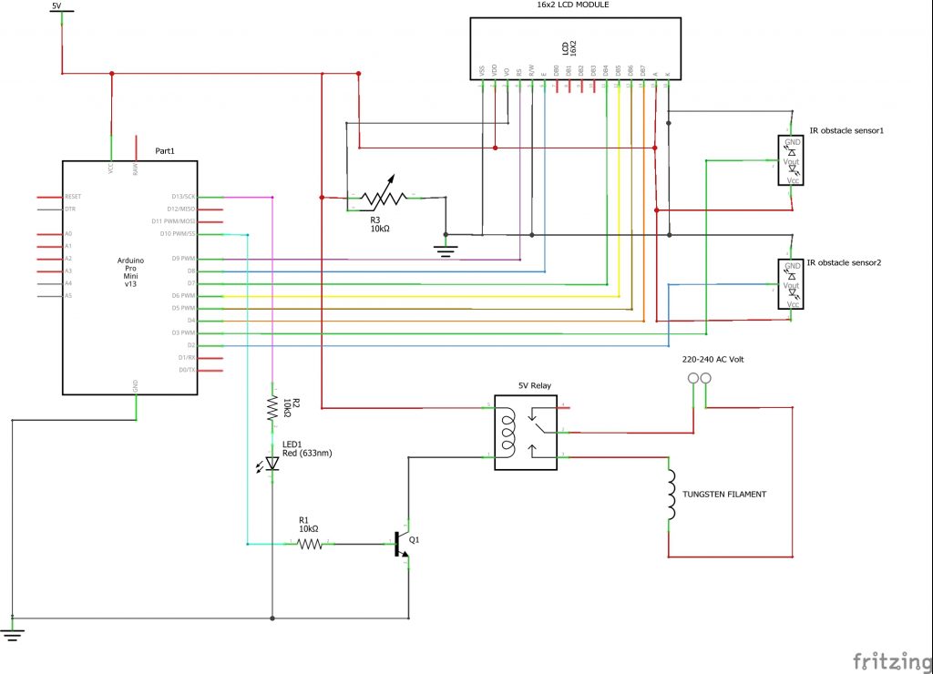
The circuit diagram for the project is shown below

Circuit Diagram Explanation
The circuit design of the project design shows that a single channel relay module can be constructed using a 5V relay, an NPN transistor like TIP41C, and a 10Kohm resistor and connected as shown in the diagram.
The usual 4-bit communication protocol was adopted in connecting the LCD to the Arduino Pro-Mini. A 2.7kohm resistor can be used to replace the 10K potentiometer used to adjust the contrast of the 16×2 LCD module.
The two IR obstacle sensors used to detect entry and exit have their output pins connected to digital pins 2 and 3 respectively on the Arduino Pro-Mini board. The design is then powered by a 5V DC and the following sketch is uploaded into the Pro-Mini board Using the FTDI ISP Programmer.
The Source Code (Arduino Sketch)
//include the LCD lib
#include <LiquidCrystal.h>
//define where the lcd pins are connected on the A. Pro Mini
LiquidCrystal lcd(9, 8, 7, 6, 5, 4);
//define where the IR sensor outputs are connectd
int irPin1 = 2;
int irPin2 = 3;
//define variables
int count = 0;
boolean state1 = true;
boolean state2 = true;
boolean insideState = false;
boolean outsideIr = false;
boolean isPeopleExiting = false;
int i=1;
//define actuator pins
#define relay 10
#define LED 13


void setup() {
  //begin serial monitor
Serial.begin(9600);
//define out input and out pin on pro mini board
pinMode(irPin1, INPUT);
pinMode(irPin2, INPUT);
pinMode(relay, OUTPUT);
pinMode(LED, OUTPUT);
//begin the lcd module
lcd.begin(16, 2);

//print a welcome msg on LCD
//set the cursor first
lcd.setCursor(0,0);
lcd.print(" WELCOME DAVID ");
lcd.setCursor(0,1);
for(int i= 0; i <15; i++){
  lcd.print(".");
  delay(100);
}
//print title of project on lcd
lcd.setCursor(0,0);
lcd.print("  BIDIRECTIONAL ");
lcd.setCursor(0,1);
lcd.print("COUNTER  PROJECT");
lcd.clear();

}


//this fxn blinks the Red LED when there is entry or exit motion
void blinkLED(){
   for(int i= 0; i <5; i++){
      digitalWrite(LED, HIGH);
      delay(50);
      digitalWrite(LED, LOW);
      delay(50);

   }
}


void loop() {
  Serial.print(!digitalRead(irPin1));
   Serial.print(" ");
  Serial.print(!digitalRead(irPin2));
    Serial.print(" ");
  Serial.println(count);
  delay(300);

if (!digitalRead(irPin1) && i==1 && state1){
     outsideIr=true;
     delay(100);
     i++;
     state1 = false;
  }

   if (!digitalRead(irPin2) && i==2 &&   state2){
    blinkLED();
    lcd.clear();
    lcd.setCursor(0, 0);
     lcd.print("ENTERING ROOM");
     outsideIr=true;
     delay(1000);
     i = 1 ;
     count++;
     lcd.clear();
    lcd.setCursor(0, 0);
    lcd.print("    CURRENT");
     lcd.setCursor(0, 1);
     lcd.print("Num in room: ");
     lcd.print(count);
     state2 = false;
  }

   if (!digitalRead(irPin2) && i==1 && state2 ){
     outsideIr=true;
     delay(100);
     i = 2 ;
     state2 = false;
  }

  if (!digitalRead(irPin1) && i==2 && state1 ){
    blinkLED();
    lcd.clear();
    lcd.setCursor(0, 0);
     lcd.print("LEAVING ROOM");
     outsideIr=true;
     delay(1000);
     count--;
     lcd.clear();
    lcd.setCursor(0, 0);
    lcd.print("    CURRENT");
      lcd.setCursor(0, 1);
       lcd.print("Num In Room: ");
      lcd.println(count);
     i = 1;
     state1 = false;
  }


//condition for AC bulb on
if(count >= 1){
  digitalWrite(relay, HIGH);
}

//turn off bulb when nobody is inside
if(count <= 0){
  digitalWrite(relay, LOW);
  lcd.clear();
  lcd.setCursor(0, 0);
  lcd.print(" NO ONE IN ROOM");
   lcd.setCursor(0, 1);
  lcd.print("LIGHT TURNED OFF");
  count = 0;
}


  if (digitalRead(irPin1)){
     state1 = true;
    }

     if (digitalRead(irPin2)){
     state2 = true;
    }

}
Visitor Bidirectional Counter Using IR sensors Arduino Code Explanation
Basically, what we did above was to define some variables and Boolean states that took care of the changes in the IR sensors when they detect IR emitting obstacles. but we used the “!digitalRead” to show or invert the IR sensor output on the serial monitor. A conditional if statements resets the Boolean states at the end of the loop function.
Results
Watch the video demonstration tutorial for more. Kindly leave us a comment below if you reproduce similar project work or a better one than this.
Conclusion
We would love to know what you think about the project and you can put a comment to ask for an upgrade of this project. Our social media handles are at the top navigator bar.
Thank you. See you next time.

