This project, Anti-Theft and Burglar System with SMS Notification, is programmed with Arduino with GSM module SIM800L, and has PIR motion sensors and laser trip mechanisms. The anti-theft and burglar system design allows specific users to arm it and disarm it by phone call or short message service (SMS). During the armed state; the systems’ motion sensors and laser mechanisms are activated to sense for intruders senses when there is an intruder within the vicinity. When the system is armed, it informs the user via SMS that it is armed and it is alert for any intrusion. The users can also arm or disarm the system at anytime by calling the system design.
Materials/Components
The following components were used in designing this project:
- Atmega328P MCU
- laser diodes
- Light dependent resistors (LDRs)
- Passive Infrared Sensors
- GSM module, SIM800L
- A house model
To design the Atmega328P MCU, we followed the circuit diagram shown below.
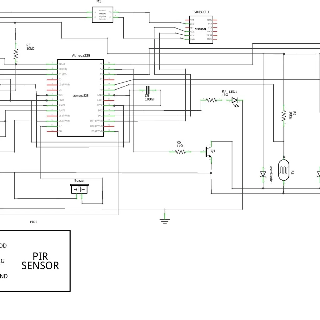
Download full circuit diagram here or Download it here
Anti-Theft and Burglar System with SMS Notification: Circuit Design Explanation:
As shown in the circuit diagram, the design used two PIR sensors; with these, we sensed motions or movements around a vicinity. Using the PIR in a timed sequence and adding a laser trip wire (using laser diodes and LDRs) would help us, as would modelling a house model. Around the windows where burglars have high tendencies of prying the glasses or closures. We added two PIR sensors to window view post. The system would be set to enter “armed state”; which is the state that the burglar(s) can trip the laser wire that is kept at a respected distance between the window and doors. The tripping would be caused by when the thief breaks the continuous light emitted by the laser onto the surface of the LDR. Then this breaking would make the design to go into the “burglary detect state”. This works a great deal with the PIR and the very close of the stranger to the user’s windows or door. Because in this state, the stranger is almost at the window, and once the PIR detects this illegal motion, it gives off loud varying siren tones through a very loud 12V electronic siren buzzer. And it automatically sends an SMS alert to the user, telling him or her that strange movement occurred at his door or window during such a time as possible while they were not aware or asleep; maybe perhaps gone out. The siren dies down after a while when it is no longer sensing movement within its line of sight.
Circuit Diagram Mode of Operation:
For this project, Anti-Theft and Burglar System with SMS Notification. The MCU is selected to be a 28-pin Atmel Atmega328P. The atmeag328P chip has four (4) pins for power. Pins 7 and 20 are for VCC power rails, while pins 8 and 22 are for GND power rails. The hardware reset pin, pin 1 is connected to a 10kΩ precision resistor to keep the pin at 5V HIGH. This pin is an ACTIVE LOW pin. This means the pin would reset the MCU when pulled to the ground (GND) hence the 10kΩ is a pullup resistor. The pin 9 and 10 of the MCU is connected to a 16Mhz crystal oscillator that helps with the pulse clocking and synchronization of internal operations of the MCU. We used the pin 2 and 3 of the MCU for programming it. Since these pins are the UART pins. Also known as the Receiver (Rx) and Transmitter (Tx) pins. These pins would form a crucial part in the FTDI pin connection as we would be using them to communicate between the MCU and the programming PC. Two 22pF capacitors are connected from pin 9 and pin 10 to GND, respectively. This would help in sinking the noise generated by the internal switching of the MCU. To ensure that the MCU accepts programs onto its RAM, we soldered two 100nF ceramic capacitors between pin 20 and pin 22 and then between pin 1 (RST) and the CTR pin of the FTDI header pins.
Anti-Theft and Burglar System with SMS Notification: Testing the MCU
To test if the microcontroller is accepting programs burned into it; we plugged the FTDI ISP programmer into the male header pin ISP input. We open the Arduino IDE and uploaded two programs: The Bare Minimum program and the Blink program.
Bare Minimum Sourcecode
void setup() {
}
void loop() {
}

Blink Sourcecode:
#define testLedPin 13
void setup() {
pinMode(testLedPin, OUTPUT);
}

void loop() {
digitalWrite(testLedPin, HIGH);
delay(500);
digitalWrite(testLedPin, LOW);
delay(500);
}
After uploading this source code to the MCU, the LED connected to pin 19 on the MCU starts blinking. We were so sure that the MCU is working to specification.
We needed a smart display to show the status of the alarm and when it is ‘armed’ and when it is ‘disarmed’. For this function, we used a 16×2 LCD module. The configuration to the MCU is done using 4-bit protocol as shown in the circuit diagram. The Vcc and GND pins of the LCD is connected to 5V and 0V power rails. The Vo is connected to the wiper pin of a 10kΩ potentiometer resistor or a 4.7kΩ connected to Vo then to ground. The register select (RS) pin is connected to pin 13 (PCD08) of the MCU while the enable (E) pin is connected to pin 14 (PCD09). These pins are very important to ensure the LCD screen display the characters that we need it to display. The read/write (R/W) pin of the LCD is grounded. And since we are using a 4-bit communication protocol; we connected four wires from D4 through D7 corresponding to pin 15 through 18 (PCD09 through PCD12) on the MCU. These data pins are very essential and cannot be overlooked when communicating microcontrollers. The LED(+) pin is connected to 5V power rail to ensure backlight brightness comes on when powered on. And finally, the LED(-) pin of the LCD, pin 16 is connected to ground or Vss.
//The following sourcecode is in C/C++ program using Arduino as IDE
// include the library code:
#include <LiquidCrystal.h>

// initialize the library with the numbers of the interface pins
LiquidCrystal lcd(7, 8, 9, 10, 11, 12);

void setup() {
  // set up the LCD's number of columns and rows:
  lcd.begin(16, 2);
  // Print a message to the LCD.
  lcd.print("hello, world!");
}

void loop() {
  // set the cursor to column 0, line 1
  // (note: line 1 is the second row, since counting begins with 0):
  lcd.setCursor(0, 1);
  // print the number of seconds since reset:
  lcd.print(millis() / 1000);
}
The SIM800L GSM was interfaced as shown in the circuit above. But since the MCU uses 5V logic and the Sim800L module uses 3.3V, we needed a voltage shifter. We connected a DC-DC buck converter to the output of the two LiPo batteries that were in series connection(This was later replaced with a 5V power supply module). The SIM800L connection to the MCU was software serial connection, which means that it could be altered in the programming syntax.
The idea was to arm and disarm the system using phone calls. After much tinkering and testing, we were able to send SMS from the GSM module and make it receive calls from authorized callers. Thus using this call times to ‘arm’ or ‘disarm’ the system design.
Finanly, we interfaced the PIR sensors, laser diodes and the LDRs but then we came across a flaw in the design.
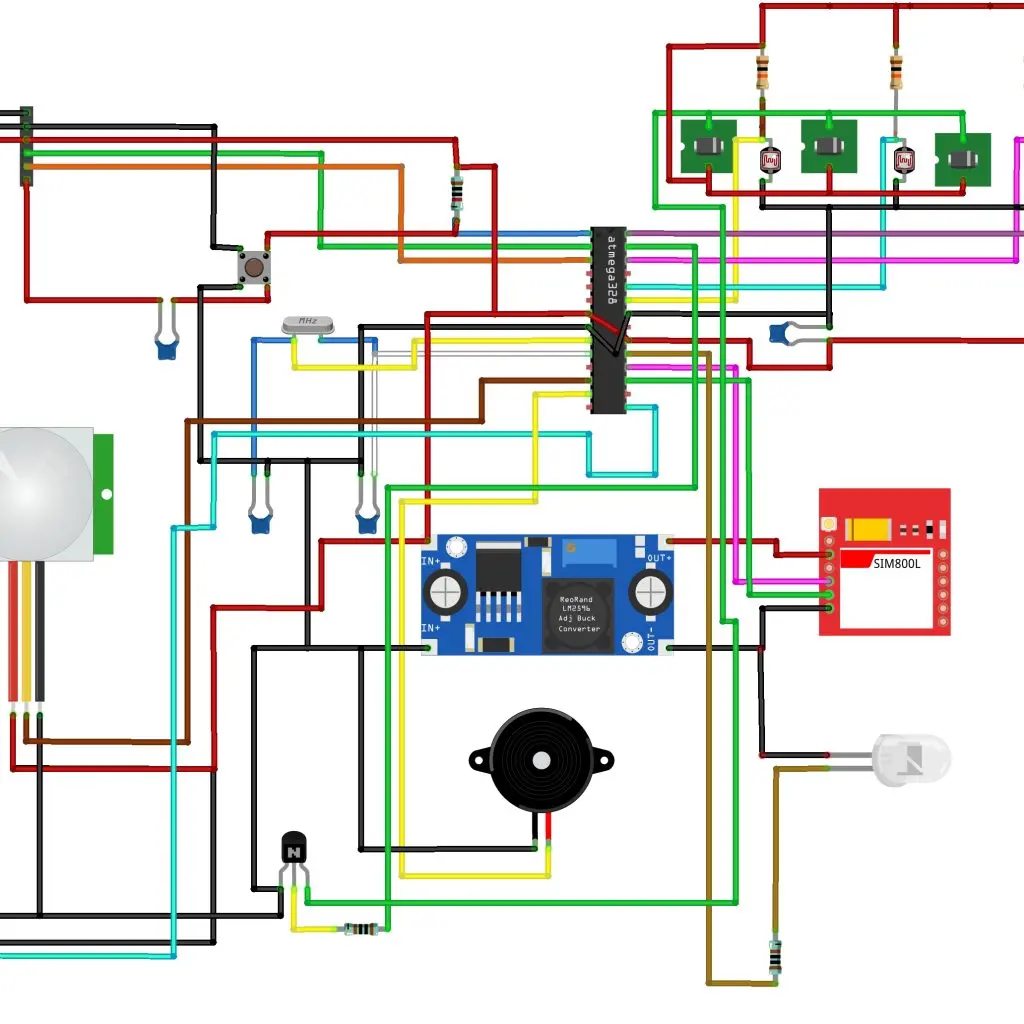
Limitations and modification of the circuit diagram:
The Anti-Theft and Burglar System with SMS Notification circuit diagram shown above was limited in function because it had only two PIR sensor and two laser diode to cover the front view and the back view of the compound model. This left a lot of blind spots for burglars to access and penetrate the vicinity. Also, we were already knowing the status of the security design with SMS alert that is sent to our phone; so the LCD display was overdoing it. We needed to cover more view points in the compound. However, this meant more sensors and more pin allocations from the MCU to the sensors. We added one more PIR to the design and two more laser diodes and LDR. However, this was at the cost of the LCD module. The new circuit diagram was thus:

Further adjustment made was to remove the relay for switch the 12V high pitch siren buzzer and use loud piezo buzzer instead and using transistor as a solid state switch to switch from the microcontroller. This reduced the rate of power consumption of the components and since this was a prototype, it was very ideal not to deafen the observers during display.
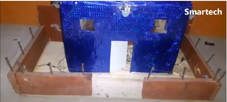
CONSTRUCTING THE HOUSE MODEL

The design for the Anti-Theft and Burglar System with SMS Notification project was modelled after a bungalow house. The design began with dimensioning and measurement of the house outlook. We envisioned that we needed a compound with four (4) sides. Hence we made a dimension of a wooden rectangular base of length 65cm x 60cm.
Still modelling off for the Anti-Theft and Burglar System with SMS Notification, The wooden base was cut with a hand saw and it was sand-papered according to ensure smoothness and splinters from entering the hands since hand gloves were not provided in the workshop. After this process, the vertical side braces which would act as the fences were cut out. For the width side of the fences, a pair of soft wood with dimensions: 60cm x 7cm x 2cm. The top of the soft wood is being installed nails and then barb-wired modeling it off from a real fence. Once this was completed; the gating system was also cut of. This has a dimension of 20cm x 2cm.

A model house is then placed inside this compound where the sensors are attached for this Anti-Theft and Burglar System with SMS Notification project. The roof of the model house is a transparent plastic glass, which helps to view the circuit design from the top view angle.
#include <EEPROM.h>
#include <SoftwareSerial.h>
SoftwareSerial cell(11, 12);

const char number1[] = {"09033827773"};
const char number2[] = {"07062174135"};
const char number3[] = {"*********"};

int8_t answer;
char aux_string[30];
char phone_number[15];
char received[15];
int length = 11;
String caller;
int counter = 0;
boolean Armed = EEPROM.read(0);
char status = "ACTIVE";

int pirPin1 = 6;
int pirPin2 = 9;
int pirPin3 = 10;

int ldrRoofPin = A0;
int ldrFrontPin = A1;
int ldrleftPin = A5;
int ldrRightPin = A3;

// Output Pins
int laserActivePin = A4;
int AlarmPin = 13;

int ldrTopSense, ldrLeftSense, ldrRightSense, ldrFrontSense;

boolean pir1Sense = true;
boolean pir2Sense = true;
boolean pir3Sense = true;

void setup() {
  //tell MCU ur outputs
  pinMode(laserActivePin, OUTPUT);
    pinMode(AlarmPin, OUTPUT);

  //tell MCU ur inputs
  pinMode(pirPin1, INPUT);
  pinMode(pirPin2, INPUT);
  pinMode(pirPin3, INPUT);

  //off Alarm
  digitalWrite(AlarmPin, LOW);
    //Begin serial communication with Arduino and Arduino IDE (Serial Monitor)
  Serial.begin(4800);
  //Begin serial communication with Arduino and SIM800L
  cell.begin(4800);
  Serial.println("Initializing...");
  delay(1000);
  while ( (sendATcommand("AT+CREG?", "+CREG: 0,1", 500) ||
           sendATcommand("AT+CREG?", "+CREG: 0,5", 500)) == 0 );
  Serial.println("Connected to Mobile Network...");


}

void loop(){
  pir1Sense = digitalRead(pirPin1);
   pir2Sense = digitalRead(pirPin2);
   pir3Sense = digitalRead(pirPin3);

 ldrTopSense = analogRead(ldrRoofPin);
 ldrLeftSense = analogRead(ldrleftPin);
 ldrRightSense = analogRead(ldrRightPin);
 ldrFrontSense = analogRead(ldrFrontPin);

Serial.print(pir1Sense);
Serial.print("  ");
Serial.print(pir2Sense);
Serial.print("  ");
Serial.println(pir3Sense);

Serial.print(ldrTopSense);
Serial.print("  ");
Serial.print(ldrFrontSense);
Serial.print("  ");
Serial.print(ldrLeftSense);
Serial.print("  ");
Serial.println(ldrRightSense);

//program is allways waiting for a +CLIP to confirm a call was received
  //it will receive a +CLIP command for every ring the calling phone does
  while (answer = sendATcommand("", "+CLIP", 1000)) {
    //answer is 1 if sendATcommand detects +CLIP
    if (answer == 1)
    {
      counter ++; // INCREMENT THIS VARIABLE FOR EACH RING.
      Serial.println("Incoming call");
      Serial.println(counter);
      for (int i = 0; i < 15; i++) {
        //read the incoming byte:
        while (cell.available() == 0)
        { delay (50); }
        //stores phone number
        received[i] = cell.read();
      }
      cell.flush();
      byte j = 0;
      //phone number comes after quotes (") so discard all bytes until find'em
      while (received[j] != '"') j++;
      j++;
      for (byte i = 0; i < length; i++) {
        phone_number[i] = received[i + j];
      }
    }
    for (int i = 0; i < length; i++) {
      // Print phone number:
      Serial.print(phone_number[i]);
      caller += phone_number[i];
         }
    Serial.println("\n>>>" + caller);

    //After 3 RINGs compare the caller ID with the authorized list then take decisions.
    if(counter > 3){
    if(caller != number1 && caller != number2 && caller != number3){
      Serial.println("Unknown Caller");
      sendATcommand("ATA", "OK", 500);
      Serial.println("I just picked to HangUp");
      sendATcommand("ATH", "OK", 500);
      }
    else {
       Serial.println("Authorized Caller");
       sendATcommand("ATH", "OK", 500);
       Serial.print("I Know You MASTER, no need to pick.");
       Armed = !Armed;
       EEPROM.update(0, Armed);
       counter = 0;

   if(Armed){
    Serial.print("Armed ");
     sendSMS("07062174135", "Alarm Armed. \nThank You.");
     sendSMS("09033827773", "Alarm Armed. \nThank You.");
     updateSerial();
  delay(500);
    delay(3000);
   }
   else{
    Serial.print("Not Armed");
    sendSMS("07062174135", "Alarm Disarmed. \nThank You.");
    sendSMS("09033827773", "Alarm Disarmed. \nThank You.");
    updateSerial();
  delay(500);
   delay(3000);
   }

   }
       }
  }

 if(Armed == 1){
    Serial.println("\nArmed");
analogWrite(laserActivePin, 225);
digitalWrite(AlarmPin, LOW);
   Serial.println("LASER ON");
    while(pir1Sense){
            analogWrite(AlarmPin, 255);
            Serial.println("\nALARM now ACTIVE");
            sendSMS("07062174135", "Intrusion Detected At left Window.");
            sendSMS("09033827773", "Intrusion Detected At left Window.");
            updateSerial();
            return;
         }
      while(pir2Sense){
      analogWrite(AlarmPin, 255);
      Serial.println("\nALARM now ACTIVE");
      sendSMS("07062174135", "Intrusion Detected At Front Entrance.");
      sendSMS("09033827773", "Intrusion Detected At Front Entrance.");
      updateSerial();
      return;
     }
   while(pir3Sense){
    analogWrite(AlarmPin, 255);
    Serial.println("\nALARM now ACTIVE");
     sendSMS("07062174135", "Intrusion Detected At Right Window.");
     sendSMS("09033827773", "Intrusion Detected At Right Window.");
     updateSerial();
    return;
   }

   //check when it is dark
       if(ldrLeftSense < 950) {
         digitalWrite(AlarmPin, HIGH);
    Serial.println("\nALARM now ACTIVE");
    sendSMS("07062174135", "Laser Tripped At Right Fence Side.");
    sendSMS("09033827773", "Laser Tripped At Right Fence Side.");
    updateSerial();
    return;
    }
  if(ldrRightSense < 950){
      digitalWrite(AlarmPin, HIGH);
    Serial.println("\nALARM now ACTIVE");
     sendSMS("07062174135", "Laser Tripped At Left Fence Side.");
     sendSMS("09033827773", "Laser Tripped At Left Fence Side.");
     updateSerial();
     return;
  }

  if(ldrFrontSense < 950){
   digitalWrite(AlarmPin, HIGH);
    Serial.println("\nALARM now ACTIVE");
     sendSMS("07062174135", "Laser Tripped At Front Fence Side.");
     sendSMS("09033827773", "Laser Tripped At Front Fence Side.");
     updateSerial();
     return;
  }
  }

     if(Armed == 0){
      Serial.println("\n Not Armed");
analogWrite(laserActivePin, 0);
digitalWrite(AlarmPin, LOW);
   Serial.println("LASER OFF");
     }
caller = "";
 }


 void sendSMS(char receiver[11], char content[140])
 {
   cell.println("AT+CMGF=1");
   delay(1000);
   cell.print("AT+CMGS=");
   delay(5);
   cell.print(char(34));
   delay(5);
   cell.print(receiver);
   delay(5);
   cell.println(char(34));
   delay(5);
   cell.print(content);
   delay(50);
   cell.println(char(26));
   delay(2000);
   Serial.println("Done");
   delay(3000);
}


void updateSerial()
{
  delay(5);
  while (Serial.available())
  {
    cell.write(Serial.read());//Forward what Serial received to Software Serial Port
  }
  while(cell.available())
  {
 Serial.write(cell.read());//Forward what Software Serial received to Serial Port
  }
}


int8_t sendATcommand(char* ATcommand, char* expected_answer, unsigned int timeout) {

  uint8_t x = 0,  answer = 0;
  char response[100];
  unsigned long previous;

  memset(response, '\0', 100);    // Initialice the string

  delay(100);

  while ( cell.available() > 0) cell.read();   // Clean the input buffer

  cell.println(ATcommand);    // Send the AT command

  x = 0;
  previous = millis();

  // this loop waits for the answer
  do {
    // if there are data in the UART input buffer, reads it and checks for the asnwer
    if (cell.available() != 0) {
      response[x] = cell.read();
      x++;
      // check if the desired answer is in the response of the module
      if (strstr(response, expected_answer) != NULL)
      {
        answer = 1;
      }
    }
    // Waits for the asnwer with time out
  } while ((answer == 0) && ((millis() - previous) < timeout));

  return answer;
}
Conclusion
Now we have shown you how we achieved this project, Anti-Theft and Burglar System with SMS Notification. Kindly let us know if you were able to build such similar project or a better version. We will be very glad to help you the best we we can. Let us know if you have any further questions in the comment section. You can also drop a suggestion too! To join the conversation, join our Telegram community, Telegram, Facebook page, Instagram and Twitter.